Do you currently have an Arduino and want to make it smaller for cheap? The Quasi-duino is for you (Italian for almost-duino). This makes a functional “almost” Arduino, in a very small form factor using the narcoleptic library for pico-power operations on a pico-space breadboard. This ‘ible will use Arduino 1.0. All of your Arduino code that you have made does not have to be formatted for the Quasi-duino!
I have found multiple places that you can use your Arduino without a crystal, voltage regulator, USB interface, or even without the reset button. These can all make a difference in your project. With the Quasi-duino, I wanted to use the minimum possible components, minimum possible power, but still with the basic Arduino capabilities.
**This project will require you to download a new Arduino core for the Quasi-duino that I developed. It is provided later in the instructable.
Please feel free to post comments and questions.
Step: 1 Parts
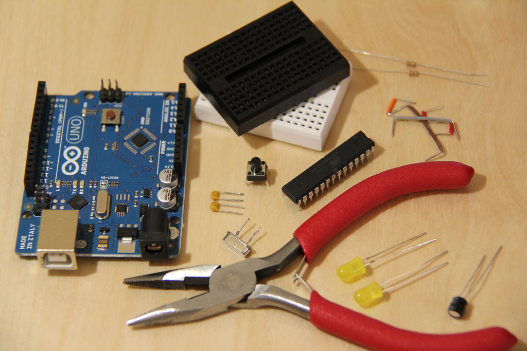
Tools:
Needle Nose Pliers (Everyone should get a pair of these anyways)
The Quasi-duino core (will explain later)
The Narcoleptic library for Arduino (compatible with Arduino 1.0)
You can get all of the parts you need at Sparkfun:
** Essential Parts for Quasi-duino ($8.75)
Mini Breadboard http://www.sparkfun.com/products/7916 $3.95
Mini Push Button Switch – Tall (Most of you will want the tall button because it is easier to incorporate in your project) http://www.sparkfun.com/products/8605 $0.50
ATmega328p http://www.sparkfun.com/products/9061 COM-09061 $4.30
Some Jumpers
** The following items need to be purchased only once, and can be used to make multiple Quasi-duinos later ($3.10)
Resistor-330 Ohm http://www.sparkfun.com/products/8377 $0.50
16MHz Crystal (needed for bootloading, but not for the completed project) http://www.sparkfun.com/products/536 $0.95
22pf Capacitors (2) http://www.sparkfun.com/products/8571 $0.50
LEDs (2) http://www.sparkfun.com/products/532 $0.70
10uf Capacitor (for disabling the auto-reset on you Arduino UNO) http://www.sparkfun.com/products/523 $0.45
Extra Breadboard (nothin’ special, just a basic one for LEDs)
Arduino UNO or later (Most of you will have one already) ** for users of older Arduinos, please see the bottom
**Optional
LiPo (get these at Sparkfun too, they’re cheap and rechargeable for your small projects!)
LiPo Charger (you’ll need one of these if you’re getting the LiPos)
** Note for users of old Arduinos: You can try an older Arduino in this project, but I have not tested them yet. You still should be able to do this project. I will make notes on the bottom of the pages that (I think) are different for older Arduinos.
Step: 2 Assemble Away!
The pictures should help you complete assembling the Quasi-duino along with the instructions below.
1. Insert the ATmega328p into the breadboard in the middle, on the end closest to you. Make sure the small dip is facing the top of the breadboard.
2. Connect a wire coming from GND (pin 8) of the left side to the very top of the breadboard.
3. Connect a wire coming from GND (this time pin 22) of the right side and connect it to the second highest point of the breadboard.
4. Take a piece of wire, enough to fit across the middle of the breadboard, and strip the whole length of it off.
5. Connect that wire across the middle of the breadboard at the second highest point.
6. Connect RST (pin 1) of the ATmega328p to the next pin on the breadboard higher.
7. Connect the top of the breadboard on the left to the next pin down.
8. Insert the button on top of the bare wire, in the middle, above the ATmega328p.
Step: 3 Bootloading the ATmega328p
Upload the latest version of ArduinoISP to your Arduino (found in the examples tab). Attach GND to GND and +5V to VCC on your Arduino and Quasi-duino. Connect MISO, MOSI, and SCK pins on the Arduino and the breadboard together (pin 17 to D11, pin 18 to D12, and pin 19 to D11). Connect the RST pin of your Quasi-duino (pin 1) to D10 on the Arduino. MAKE SURE to insert the 10uf electrolytic capacitor between RST and GND on Arduino (the long lead goes to RST). If you would like, connect one LED to D13 on your Quasi-duino and the other between VCC and GND to debug.
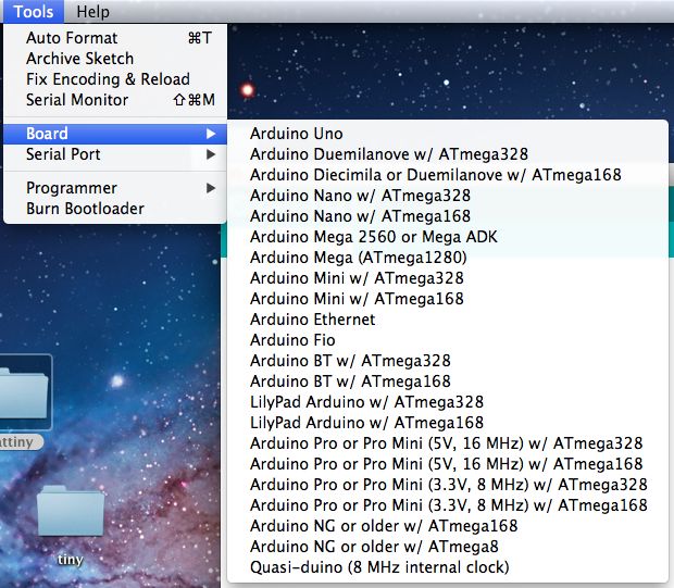
Then download the zip at the bottom of this page and put it in your hardware folder (if you do not have one, name a folder “hardware” and put it in your sketch folder). Click out of the Arduino IDE. Then click back into the Arduino IDE. Now, in the boards selection, you should see “Quasi-duino (8MHz internal clock).” This is the 8MHz internal clock selection of the ATmega328p. Now, put in your crystal from X1 to X2 (pins 9 and 10). Put your 22pf capacitors in, one between X1 and GND, and the other between X2 and GND. Select the Quasi-duino in the boards menu and burn the bootloader w/ ArduinoISP. After about a minute, you should see “Done Burning Bootloader”.
In your current Arduino, most of them will have a 16MHz external clock (the oblong shape shiny silver thing that says SPK16.000G). You might ask, “why the extra components, it’s just an extra cost.” Well, the internal clock is not as accurate, just a few microseconds off. If you were programming for a drone or just using serial communication, you will want an external crystal (the clock) for more accuracy. In most of your regular projects, you will find that most do not require an external crystal.
Other electronics components you may not need (not included in the Quasi-duino) are: a voltage regulator (for more voltage being able to come into your Quasi-duino), LEDs (but you might want to check if it gets power once in a while, but it takes about 35mA of power to run continuously), or even your USB interface. Once you program your chip for the project, you could take off the USB interface, taking off about 15uA.
I have modified the current breadboard Arduino core for this project. Now, the Quasi-duino can compile code, and upload with ArduinoISP. Previously, this was not possible with the current cores available on the Arduino site. The code at the bottom of this page is the modified Arduino core that works with the Quasi-duino.
Go to the very end of this ‘ible for error messages and how to fix them.
For more detail: The $9 Quasi-duino (Almost-duino) using ATmega328 microcontroll


