Introduction:
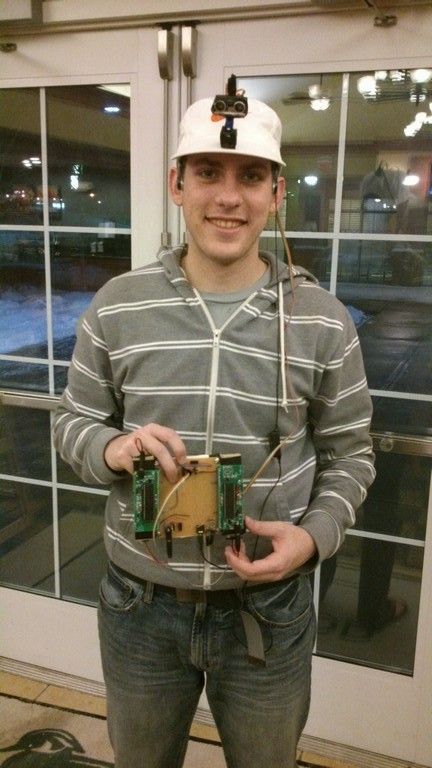
Our final project for the ECE 4760 course consists of a wearable device to provide aid for the visually impaired. An ultrasonic distance sensor located on a hat collects data of the surrounding environment scanning the area ahead of the user, and uses this data to give an audio feedback through stereo headphones. Using the principles of human sound localization this feedback provides information on the location and distance of the obstacles around the user by changing the angle and intensity of the sound produced. The goal of this project was to create a device that would help visually impaired people to move around with more ease, helping them place walls, doorways and obstacles sooner than they would if they were using only a walking stick.
High Level Design
Rationale and sources of the project idea
Background math
The physics and math of our project are based heavily on the way sound waves travel through air and the way our hearing system locates the source of a sound. If we imagine ourselves sitting at the origin of a cylindrical coordinates system, what we are trying to do is to simulate sound coming from a sound source located at several (r, θ, z) coordinates. However, we are not worrying about the coordinate z (height of the sound source) since our sensor will only scan on a two dimensional manner. Thus, we can simplify this by getting rid of the z coordinate and assuming our head is located at the origin of a 2 dimensional, polar coordinates system.
To simulate this, we must first understand how our brain locates the source of a sound when we hear it. Basically, it uses two things to do that: Difference in the time of arrival and difference of sound intensity from one ear to the other. Imagine a sound source located at coordinates (r, 0), right in front of the head. The distance between the source and each of the ears is exactly the same, so a sound wave generated by this source would reach both of them at the exact same time and with the same intensity. However, if we change our sound source to a coordinate (r, 45o), for instance, the length from the source to the left ear is smaller than to the right, so the sound wave would reach the right ear with a slight delay in time and also with some attenuation.
We must then find this distance difference between both paths to find out how much time passes between when the wave reaches the left ear and when it reaches the right one for a given angle 900 > θ > 0o. This can be easily done with simple geometry if we make two simplifications. We must consider the sound source at a distance r = ∞ from the head, so that the paths from the source to each ear can be considered parallel, and we must consider the head as being a circle of diameter d, d being the length between ears. The results can then be duplicated for angles between 0o and -90o.
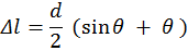
For these values of θ the path to the left ear is always shorter, as it is a straight path. For the right ear, though, the sound will travel straight until it collides with the head, when it will then by diffraction circle around it until it reaches the right ear.
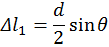
First, we calculate the extra length Δl1 that the right wave travels between when the left wave hits the left ear and the right wave hits the head. According to the figure, we can see that this distance is given by:

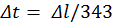
After that, finding the time difference is pretty trivial, knowing that the speed of sound is 343 m/s.
Logical Structure
For the sound generation, the Direct Digital Synthesis (DDS) technique, introduced to us in the ECE 4760 Laboratory 4 (Fall 2013), was used. Using the Fast PWM mode on Timer 0, two outputs are generated on ports B3 and B4 corresponding to the left and right stereo channels respectively. The two PWM outputs are then low-pass filtered via hardware, what results in a nice sinusoidal wave to connect to the earphones. These two channels can be controlled separately, being possible to activate one and after the correct delay activate the second one. It is also possible to change the intensity of each one separately, as well as together. The first is useful to create the volume difference between channels, while the latter is for the overall volume control.
The audio feedback comes in the form of a series of beeps that will change in intensity and location according to the information sent by the sensing MCU. The location actually reflects the position currently being scanned by the sensor. So, if the device is gathering information about your far left side, the user would hear a sound coming from that spot. All the temporization of this routine is made by Timer 2. It controls the length of the beeping sound that is sent to the earphones, the interval between each beep and the delay between the channels. Also, it is this routine that dictates when the necessary changes in frequency, delay and volume will occur: Only during the intervals between each beep, otherwise the user might get confused. The Timer 2 Interrupt routine consists of a 4 state state-machine that controls the outputs of the Timer 0 PWM. Every time this ISR is called, the Top value of the timer is updated to reflect the next time interval that must be counted (length of the beep, interval between beeps or time delay between channels), the pertinent channel is turned on or off, and the machine moves to the next state.
Hardware/Software Tradeoffs
We opted to use an extra MCU, and all the hardware that comes with it, to have more processing power for all the tasks that must be done. The DDS uses a lot of it since the PWM is always running and its ISR is called very frequently. Also, since two completely independent sine waves have to be generated, the ISR takes a long time to complete, leaving not much time between one routine and the next to perform the rest of the program. Since the other timing procedures such as the delay time, the motor control and the distance sensing require some accuracy, putting them all together on the same MCU might cause some ISR to not be attended, or take too much time to attend others, which could cause the whole system to misbehave.
Another tradeoff was to choose a cheaper and simpler ultrasonic sensor, which required software distance calculation, instead of a better, more expensive one with an integrated circuit that would give us the distance already calculated and ready to use. We came to the conclusion that the few dollars saved were not worth the trouble of designing and debugging the sensing program, which showed to be the cause of a lot of issues.
Parts List:
| art | Vendor | Unit Price | Quantity | Price |
| TowerPro SG90 | Amazon | $ 3.00 | 1 | $ 3.00 |
| SainSmart HC-SR04 | Amazon | $ 5.00 | 1 | $ 5.00 |
| 9V Battery Connector | Amazon | $ 1.56 | 3 | $ 4.68 |
| 3.5mm Connector | Digikey | $ 0.68 | 1 | $ 0.68 |
| 6’’ Solder Board | ECE 4760 Lab | $ 2.50 | 1 | $ 2.50 |
| 9V Battery | ECE 4760 Lab | $ 2.00 | 3 | $ 6.00 |
| Custom PC Board | ECE 4760 Lab | $ 4.00 | 2 | $ 8.00 |
| Mega1284 | ECE 4760 Lab | $ 5.00 | 2 | $ 10.00 |
| Header/Plug | ECE 4760 Lab | $ 0.05 | 107 | $ 5.35 |
| 330Ω Resistor | ECE 4760 Lab | $ – | 3 | $ – |
| 1KΩ Resistor | ECE 4760 Lab | $ – | 2 | $ – |
| 5.1KΩ Resistor | ECE 4760 Lab | $ – | 2 | $ – |
| 75Ω Resistor | ECE 4760 Lab | $ – | 1 | $ – |
| 1uF Capacitor | ECE 4760 Lab | $ – | 1 | $ – |
| 0.1uF Capacitor | ECE 4760 Lab | $ – | 1 | $ – |
| 10nF Capacitor | ECE 4760 Lab | $ – | 2 | $ – |
| Power Plug | ECE 4760 Lab | $ – | 1 | $ – |
| Flat Cable | LASSP Stock Room | $ 1.80 | 1 | $ 1.80 |
| Earphones | Pre-owned | $ 5.00 | 1 | $ 5.00 |
| LM7805 | RadioShack | $ 2.00 | 1 | $ 2.00 |
| Hat | TJMax | $ 7.00 | 1 | $ 7.00 |
| Total | $ 61.01 |
For more detail: Ultrasonic Pathfinder Using Atmega1284