Introduction
-Project Sound Bite
For our ECE 4760 final project, we designed and implemented an ultrasonic range-finding hat that uses haptic feedback to alert its wearer about obstacles in his or her path. The hat is equipped with an ultrasonic transmitter/receiver circuit, which is capable of emitting short pulses of ultrasonic-frequency (approximately 40 kHz) sound, at a level of about 120 dB. These pulses then echo off the closest object in the line of sight of the hat and are picked up by the receiver. The time delay between sending the initial pulse and receiving the echo gives a sense of how far away the obstacle is from the ultrasonic sensor, which can be conveyed to the person by vibrating the hat at a level proportional to that distance. This allows the person to understand what obstacles are in his or her path and to respond accordingly. Specifically, this project is intended as a proof-of-concept/prototype for a product that would ultimately be used by sight-impaired individuals to detect walls or other obstructions, reducing their dependency on canes.
High Level Design
Rationale and Source of Our Project Idea
Many animal species utilize echolocation to identify prey or to better understand their surroundings. Arguably, the most famous implementation of this technique in the animal kingdom is the use of ultrasonic echolocation by bats to understand the size, distance, and characteristics of their prey (insects). However, the use of these principles need not be limited to bats and other animals, but could help humans with guidance and navigation as well, especially humans who are blind and have difficulty understanding their surroundings using “normal” senses. Therefore, the rationale for this project was to design a system that is built upon the principles of ultrasonic echolocation to allow a person with a disability to get around and understand their surroundings more easily.
Background Math
The mathematical foundation for this project is very simple and is primarily based upon acoustic velocity, or the speed of sound, and the time it takes sound to travel a certain distance. At a basic level, this is governed by the following equations:
- Approximate speed of sound in air: v = 331.4 + 0.6T, where T is the temperature in °C
- Round-trip distance = v*t, where t is the time for the pulse to return to the sensor
- Object distance (approximate) = 39*(Round-trip distance)/2 inches
For this project, the speed of sound in dry air at 20 °C and 1 atmosphere pressure was used, which is approximately 343.2 m/s. This value was multiplied by the time difference between when the initial ultrasonic pulse was sent and the echo was received, which gives the round trip distance that the ultrasonic pulse travelled. However, we are interested in the distance to the object off which the pulse echoed, which is half the round trip distance. There are approximately 39 inches per meter, so the object distance in meters is multiplied by 39 to convert the distance to inches. This is the only major calculation done in the main loop of the software.
Logical Structure
The Bat Hat system is structured into four main stages: the pulse transmission stage, the echo detection stage, the distance computation stage, and the pulse width modulation (PWM)/haptic feedback stage. The state transition diagram below reflects the flow of these states during normal operation. These states represent events both in hardware and software and, aside from the distance calculation, each state can (and will in the following sections) be broken down further into hardware and software components.
At a high level, the core of the system is based around three software interrupt service routines (ISRs). One ISR, a rising and falling edge triggered external interrupt, is used to receive echoes and record their arrival times and durations. The next ISR is used to drive a consistent echo pulse train to the transmitter and reset system time when appropriate. The third ISR increments system time. The main loop of the program then updates the PWM value used to control the haptic feedback vibration motor.
The hardware is closely associated with the software. The transmitter consists of an oscillator circuit that drives the ultrasonic transmitting speaker at 40 kHz and is controlled by a single TTL pin, which is driven by a microcontroller port. This creates a train of short ultrasonic pulses, which hit the ultrasonic receiver, reflect off the nearest object, and return to the receiver. The receiver circuitry filters and amplifies the signal and drives a trigger that tells the microcontroller when there is a wave present. As was stated previously, the time between the initial pulse and the reflected pulse at the receiver, as well as the duration of the two pulses, is recorded by the microcontroller. Any further echoes are ignored because they are unnecessary for determining the distance of the nearest obstacle.
Scope trace of the initial pulse and echo, as seen at the receiver. The top trace is the received signal after amplification and filtering. The bottom trace is the trigger output, which is fed into the microcontroller.
Hardware and Software Tradeoffs
We chose to implement the most complex parts of our project in hardware. This was done in order to allow for more accurate timing and to eliminate the need for an external ADC (the microcontroller’s internal ADC samples too slowly for an ultrasonic signal). We could also get more power (higher dB) by driving the transmitter with an external source.
In software, we could have made use of a real-time kernel for timing tasks and concurrency management with semaphores, but because an ISR is never interrupted by another ISR, we could simply utilize volatile variables and a well-structured state machine to eliminate the need for the real-time kernel. This gave us more flexibility with timing in that all three timers were available for our use.
Standards
There are several international standards associated with sounds and their relationships with human beings. One major standard is ISO 532:1975, “Acoustics — Method for calculating loudness level,” which “Specifies two methods for determining a single numerical value of a given sound, the first method is based on physical measurements, such as spectrum analyses in octave bands, the second method is based on spektrum [sic.] analyses in one-third octave bands.” ISO 28961:2012, “Acoustics — Statistical distribution of hearing thresholds of otologically normal persons in the age range from 18 years to 25 years under free-field listening conditions,” shows that we are operating well outside of the human hearing range, which is related to ISO 266:1997, “Acoustics — Preferred frequencies.” Lastly, because of the haptic component of the project, ISO standard 9241-920:2009, “Ergonomics of human-system interaction — Guidance on tactile and haptic interactions,” “gives recommendations for tactile and haptic hardware and software interactions.”
Relevant Patents and Copyrights
There are two patents we found to be relevant to our project. The first is US20120299643, “Driving circuit for a circuit generating an ultrasonic pulse, in particular an ultra-sonic transducer, and corresponding driving method,” which is related to the subject matter of our project. However, the approach we use in our design is very different from that in the patent. Another applicable patent is WO2012123787, “An echolocation apparatus,” which, according to the Abstract, “comprises an echolocation module configured to determine a distance to the object based on the received sound signal reflected from an object.” This patent is not as relevant to our project, but does contain interesting ideas related to ultrasonic range-finding.
Additionally, we do make use of the “uart.c” and “uart.h” files, which are under “The Beer-Ware License” and were written by Joerg Wunsch. This is the only copyrighted software we use. There are no other relevant copyrights or trademarks, as far as we know.
Hardware
Overview
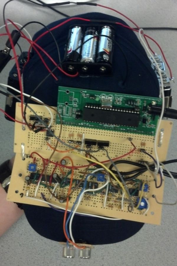
The centerpiece of our hardware is the ultrasonic transmitter and receiver board. This consists of an oscillator circuit used to drive the transmitter at 40 kHz, with a peak-to-peak voltage of 24 V. The input to the oscillator circuit comes from the ATmega1284p microcontroller. The output of the receiver circuitry is fed back into the microcontroller. Additionally, there is an optoisolating circuit used to separate the haptic feedback motor from the rest of the circuitry. The input of this optoisolator circuit is the PWM output of the microcontroller. Lastly, there is a series of switches, which connect the battery packs to the circuitry to provide the necessary voltages (+/- 12 V for the op-amps and microcontroller and 5 V for the haptic feedback motor). An overview of the hardware can be seen in the image below.
Transmitter
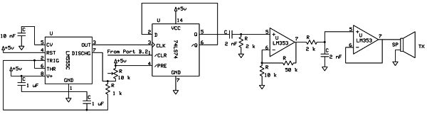
The transmitter circuitry consists of a 555-timer, which is fed into a D flip-flop, the output of which is high pass filtered, amplified, low pass filtered, and ultimately fed to the input of the ultrasonic transmitter. A block diagram showing the signal flow through the transmitter circuit is below. Refer to Appendix B for a schematic of the ultrasonic transmitter circuitry.
555 Timer
The 555 timer generates an 80 kHz signal with an duty cycle that is corrected by the D-flip flop. The 555 timer is operating in astable mode.
TTL D Flip-flop
The D flip flop acts as a frequency divider (by a factor of 2) and as an on-off switch. As a result of frequency division, the output is a 40 kHz signal with a 50/50 duty cycle (i.e. a square wave). The CLR feature of the D-flip flop is used to turn on and off the signal without the warm up time that a 555 timer would require. The CLR input is connected to Port B.2 of the microcontroller. The image below shows the sound pulse sent to the transmitter when B.2 goes high.
Parts List:
| Part | Vendor | Cost/Unit | Quantity | Total Cost |
|---|---|---|---|---|
| Atmega 1284p | Lab Stock | $5 | 1 | $5 |
| Custom PCB | Lab Stock | $4 | 1 | $4 |
| 40 kHz Tx/Rx Pair (Part #139492) | Jameco Electronics | $7.95 | 1 | $7.95 |
| Vibrating Mini Motor Disc (Part #1201) | Adafruit Industries | $1.95 | 1 | $1.95 |
| Large Solder Board | Lab Stock | $2.50 | 2 | $5 |
| Header Pin | Lab Stock | $0.05 | 50 | $2.50 |
| SPDT Switch | Lab Stock | $0.73 | 3 | $2.19 |
| LM 353 Op-amp | Lab Stock | $0 | 9 | $0 |
| Hat | Target | $3.95 | 1 | $3.95 |
| AA Battery | Target | $0.42 | 7 | $2.94 |
| 9V Battery | Target | $1.57 | 2 | $3.14 |
| Potentiometer | Lab Stock | $0 | 4 | $0 |
| Wires, Resistors, Capacitors | Lab Stock | $0 | Many | $0 |
| TOTAL: | $38.62 |
For more detail: The Bat Hat Using Atmega1284