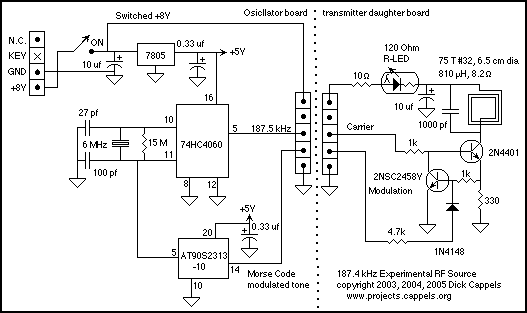
Summary of 1750 Meter Lowfer Band amplitude modulated RF source using ATtiny2313 microcontroller
This project is a low-power 187.5 kHz RF signal source designed for experimental receiver work within the US Part 15 FCC regulations, allowing up to 1 watt output on 160-190 kHz with a limited antenna length. The oscillator uses a 74HC4060 IC running at 6 MHz, divided down to 187.5 kHz, with modulation input from a microcontroller sending Morse code. The output stage is a gated current source using transistors and a parallel-tuned circuit to drive a loop antenna with only a few milliwatts, ensuring compliance with FCC power limits.
Parts used in the 1750 Meter Lowfer Band amplitude modulated RF source:
- 74HC4060 oscillator/divider IC
- Crystalline oscillator (crystal in socket)
- 2N4401 transistor
- 2NSC2458Y transistor
- 330 Ohm resistor
- LED with internal 100 Ohm resistor (or LED plus 120 Ohm resistor if no internal resistor)
- 10 μF capacitor
- 9V transistor radio battery (power supply)
- Microcontroller (ATtiny2313) for Morse code modulation
- Parallel tuned circuit (resonant loop antenna)
This is a low power signal source I put together one evening to provide 187 KHz RF signals for an anticipated receiver investigation. Under Federal Communications Commission rules inside the United States, one is allowed to operate a transmitter without a license under certain conditions. Here, I have copied the relevant section of the most recent version of the Code of Federal Regulations that I could find..

CHAPTER I–FEDERAL COMMUNICATIONS COMMISSION
PART 15–RADIO FREQUENCY DEVICES–Table of Contents
Subpart C–Intentional Radiators
Sec. 15.217 Operation in the band 160-190 kHz.
(a) The total input power to the final radio frequency stage(exclusive of filament or heater power) shall not exceed one watt.
(b) The total length of the transmission line, antenna, and ground lead (if used) shall not exceed 15 meters.
(c) All emissions below 160 kHz or above 190 kHz shall be attenuated at least 20 dB below the level of the unmodulated carrier. Determination of compliance with the 20 dB attenuation specification may be based on measurements at the intentional radiator’s antenna output terminal unless the intentional radiator uses a permanently attached antenna, in which case compliance shall be demonstrated by measuring the radiated emissions.
If you are thinking seriously about building a Part 15 transmitter, I suggest you read through Part 15 to make sure you are fully compliant. The FCC provides for very heavy penalties for those who step out of line.
Here is where I found this copy of Part 15:
However poor the efficency of the antennat some people using sophisticated coding and dedecoding techniques have managed to communicate over thousands of miles in this band (160 to 190 kHz), all operating within the scope of Part 15. Amazing.
In order to get started tinkering with circuits on this band, I put together a low power signal source.
This signal source only supplies a few milliwatts to the output stage when the +8V input is supplied by a 9V transistor radio battery. The low power in the output stage results from the collector load being a parallel tuned stage, thus it is a high impedance at resonance.

Circuit Description
Oscillator and divider
The 74HC4060 oscillates at 6.000 MHz, and is divided by 32 to get 187.5 kHz. Pin 5 of the CD4060 is a 732 Hz square wave which can be used to modulate the output stage rather than using a micro controller, but in this instance, the modulation is supplied by a micro controller that I programmed to send Morse code to the modulation input, with the Morse code modulated by an audio frequency square wave, resulting in tone modulated AM (Mode A2) being transmitted.
Output Sage
The output stage is a gated current source driving a resonant loop antenna. The emitter current of the 2N4401 causes a voltage drop across the 330 Ohm resistor. The 2NSC2458Y reduces the amplitude of the 187.5 kHz carrier signal on the base of the 2N4401 so that the maximum voltage across the 330 Ohm resistor is 0.6 volts, the base-emitter voltage of the 2NSC2458Y. The 0.6 volt drop across the 330 Ohm resistor means that peak emitter current for the 2N4401 is about 1.8 milliamps peak emitter current. Since the collector current is approximately equal to emitter current, this results in the resonant circuit on the collector of the 2N4401 being driven by a 1.8 milliamp square wave.
