
Summary of Frequency Meter with 100 MHz RF desktop channel using ATtiny2313 microcontroller
Summary:
This article describes a frequency meter section built around the AT90S2313 microcontroller, integrated with a 100 MHz RF interface. The device measures frequencies up to 4 MHz, counting values up to 65535. Users can select time bases ranging from 10 ms to 100 seconds via an RF keyboard link. The firmware combines code from two previous projects, and the system communicates using specific RS-232 to RF data channel addresses. A 5-volt zener diode is recommended for input protection against electrostatic discharge.
Parts used in the Frequency Meter Project:
- AT90S2313 microcontroller
- 100 MHz RF interface
- RS-232 to 100 MHz RF desktop channel adapter
- Keyboard (RF link)
- 5 volt zener diode (recommended for pin 9)
- Transistor (alternative reverse base-emitter junction protection)
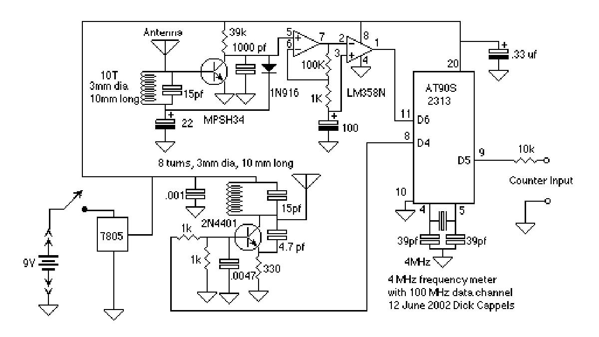
This basically the frequency meter section of the frequency meter/pulse generator based on the AT90S2313 described elsewhere on this site, combined with the 100 MHz RF interface described in the page about the RS-232 to 100 MHz RF desktop channel adapter. Built and align this is the same manner as the 100 MHz RF desktop channel adapter. The frequency meter has a maximum input frequency of 4 Mhz and counts up to 65535. Time bases of 10 ms, 100 ms, 1 second, 10 seconds, and 100 seconds are selectable from the keyboard via the RF link.
Downloads:
Assembler source
hex file
I would suggest adding a 5 volt zener from pin 9 of the AT90S2313 to ground to reduce chances of damage to the input from electrostatic discharges. I did not put it on the schematic because I did not build this and try it. Take a look at the frequency and pulse generator project on this web site to see how I used the reverse base-emitter junction of a transistor to accomplish the same thing because I didn’t have any appropriate zeners at the time of the project.
The frequency meter sends to address $02 (the RS232 to RF Data Channel receive address) and receives address $03 (which is coded as $18 in the firmware because of the position of the address within the header byte).
Firmware
This firmware was a combination of the firmware from two projects, with the irrelevant parts removed. There are several assembler warnings of registers being assigned more than once -don’t worry about it, there aren’t any conflicts but it made hooking the two pieces of code a little easier and made the resulting file a little easier to read doing it this way.
Here is the Assembler source file. In case its helpful, here is the hex file
At power-on a greeting and menu is displayed. Individual readings are taken whenever the “R” key or return key are pressed.
For more detail: Frequency Meter with 100 MHz RF desktop channel using ATtiny2313 microcontroller
- What is the maximum input frequency of this meter?
The frequency meter has a maximum input frequency of 4 Mhz. - How many counts can the device measure?
The device counts up to 65535. - Can I change the time bases on the fly?
Yes, time bases of 10 ms, 100 ms, 1 second, 10 seconds, and 100 seconds are selectable from the keyboard via the RF link. - Which address does the frequency meter send to?
The frequency meter sends to address $02, which is the RS232 to RF Data Channel receive address. - What address does the meter receive from?
The meter receives address $03, which is coded as $18 in the firmware due to the header byte position. - How do I trigger an individual reading?
Individual readings are taken whenever the R key or return key are pressed. - Is a zener diode required for the circuit?
A 5 volt zener from pin 9 to ground is suggested to reduce chances of damage from electrostatic discharges, though it was not included in the original schematic. - What happens when the device powers on?
At power-on a greeting and menu is displayed. - Where can I find the source code?
Assembler source and hex files are available for download.
