Summary of 2 Digit Up/Down Counter Circuit
This article explains a 2-digit up/down counter using microcontrollers (8051 AT89C51 or AVR ATmega8) driving two 7-segment displays. Button presses increment or decrement the displayed value from 00 to 99, with examples of circuit components, wiring notes for common-anode/cathode displays, sample code for both MCUs, operation steps, applications, and limitations (max two digits). It includes simulation/video links and discusses pull-down buttons and current-limiting resistors.
Parts used in the 2 Digit Up/Down Counter Circuit:
- AT89C51 (8051 Microcontroller)
- ATmega8 Microcontroller (alternative)
- 2 x 7-Segment Displays (Common Anode or Common Cathode as noted)
- 2 x 2N2222 NPN Transistors
- 3 x Push Buttons
- 2 x 10KΩ Resistors
- 2 x 470Ω Resistors
- 8 x 100Ω Resistors
- 11.0592 MHz Crystal
- 2 x 33pF Capacitors
- 10μF/16V Capacitor
- 1KΩ x 8 Resistor Pack
- Mini Breadboard
- 5V Power Supply
- 8051 Programmer
- 2 x 330Ω Resistors (listed for ATmega8 circuit)
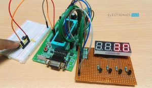
Generally, one can see the digital displays which display the score when buttons are pressed on score boards. The main heart of this score board is 2 digits up/down counter circuit. The 2 digits are displayed on two 7 segment displays. This article describes 2 digit up/down counter circuit.
2 Digit Up/Down Counter Circuit Principle:
The main principle of this circuit is to increment the values on seven segment displays by pressing the button. When button 1 is pressed value on the display is incremented by one value and when other button is pressed value on the display is decremented by one value. The value on the display can be incremented and decremented from 0-99 as it uses only 2 displays. If one wants to display 3 digits, three displays should be used .There are many circuits available for 2 digit up/down counter but using a microcontroller reduces components and space on the board but simple programming is required.
Also Read the Related Post – Frequency Counter Circuit
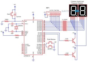
Two Digit Up Down Counter Circuit Diagram
Circuit 1: Using 8051 Microcontroller
 Do you know How a Bidirectional Visitor Counter Circuit Works using 8051 Microcontroller?
How to Operate 2 Digit Up/Down Counter Circuit?
Components Required
- AT89C51 (8051 Microcontroller)
- 2 X 7-Segment Displays (Common Anode)
- 2 X 2N2222 NPN Transistors
- 3 X Push Buttons
- 2 X 10KΩ Resistors
- 2 X 470Ω Resistors
- 8 X 100Ω Resistors
- 11.0592 MHz Crystal
- 2 X 33pF Capacitor
- 10μF/16V Capacitor
- 1KΩ X 8 Resistor Pack
- Mini Breadboard
- 5V Power Supply
- 8051 Programmer
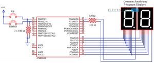
Circuit 2: Using ATmega8 Microcontroller
Components Required
- ATmega8 Microcontroller
- 2 X 7-Segment Displays (Common Anode)
- 2 X 10KΩ Resistors
- 2 X 330Ω Resistors
- 2 X Push Buttons
Circuit Design of 2 Digit 7-Segment Up Down Counter
The 2digit Up/Down counter consists of two seven segment displays connected to ATMEGA8 microcontroller. The seven segment display consists of 8 pins and one common pin.
There are mainly two types of seven segment displays 1) common cathode 2) common anode. The display here used is common cathode display. Generally for common cathode displays, common pin should be grounded and for common anode, it should be connected to VCC.
In Seven segment display, there are seven segments and they are similar to seven LEDs. Seven pins belong to these seven segments where as the last pin is dot at the coner of the display. For common cathode, display assigning logic1 to the segment pin glows particular segment. In case of common anode, the segment pin should be assigned logic0 in order to glow the segment. Each segment is given one name starting from ‘a ‘and last segment dot is ‘h’.
In our circuit, seven segment display is connected to micro controller through a current limiting resistor of 330 ohms. Two buttons in pull- down mode are also connected.
The necessity of connecting the buttons in pull down mode is to avoid floating state of the button i.e. unknown state. If the button is connected in pull down mode, this ensures that button is initially in logic0 state.
Do you know How a Bidirectional Visitor Counter Circuit Works using 8051 Microcontroller?
Two Digit Up Down Counter – Circuit Simulation Video
How to Operate 2 Digit Up Down Counter Circuit?
- Initially, power the circuit.
- The values displaying on seven segments is ‘00’.
- Press the button 1 in the circuit. The value on the seven segments is incremented to ‘01’.
- Again press button 1. Value on the displays is ’02’.
- Now, press the second button. You can see the value decrementing to 01.
- The value on the displays can be incremented up to 99, after 99 if button 1 is pressed it starts incrementing from ‘01’. If the second button is pressed after decrementing to ‘00’, it displays ‘00’. This value can be changed only after incrementing the value atleast to ‘01’.
Algorithm for Programming
- Declare the corresponding PORTS of the microcontrollers as input or output.
- Declare an array with the seven segment codes i.e, if number one is to be displayed, then the binary value that should be passed is as follows:
dp g f e d c b a
1 1 1 1 1 0 0 1
This is because b and c segments should be assigned with logic 0 to display ‘1’, I am using a Common Anode 7-Segment Display . So, the binary value 0b11111001 or the hexadecimal value 0xf9 is assigned to the particular port on which ‘1’ is to be displayed. The array should consist of 0-9 binary or hexa values.
- Check the status of the buttons using if else loop.
- If the button 1 is pressed for first time, first seven segment (on the left) should display 0 and the other should display 1. So the output is ‘01’.
- If the button 1 is pressed for second time, value on second button should be incremented by one.
- If the second button is pressed, value on the first segment should be decremented by one value.
CODE
Code for 8051 Microcontroller
| #include<reg51.h> | |
| #define SEGMENT P0 | |
| sbit switch1=P3^0; | |
| sbit switch2=P3^1; | |
| sbit digit1=P2^0; | |
| sbit digit2=P2^1; | |
| void delay (int); | |
| int x=0,y,z; | |
| unsigned char ch[]={0xc0,0xf9,0xa4,0xb0,0x99,0x92,0x82,0xf8,0x80,0x98}; | |
| void delay (int d) | |
| { | |
| unsigned char i; | |
| for(;d>0;d–) | |
| { | |
| for(i=250;i>0;i–); | |
| for(i=248;i>0;i–); | |
| } | |
| } | |
| void main() | |
| { | |
| switch1=1; | |
| switch2=1; | |
| digit1=1; | |
| digit2=1; | |
| while(1) | |
| { | |
| if(switch1==0) | |
| { | |
| x++; | |
| delay(200); | |
| } | |
| else if(switch2==0) | |
| { | |
| x–; | |
| delay(200); | |
| } | |
| y=x/10; | |
| SEGMENT=ch[y]; | |
| digit1=0; | |
| delay(10); | |
| digit1=1; | |
| z=x%10; | |
| SEGMENT=ch[z]; | |
| digit2=0; | |
| delay(10); | |
| digit2=1; | |
| } | |
| } |
Code for ATmega8 Microcontroller
| /* | |
| * updown_counter.c | |
| * Author: ADMIN | |
| */ | |
| /*#define F_CPU 8000000UL*/ | |
| #include <avr/io.h> | |
| #include <util/delay.h> | |
| int main(void) | |
| { | |
| DDRB = 0x00; | |
| DDRC = 0xff; | |
| DDRD = 0xff; | |
| unsigned int i,x=0,y,z; | |
| unsigned char arr1[]={0x40,0x79,0x24,0x30,0x19,0x12,0x02,0x78,0x00,0x18}; | |
| while(1) | |
| { | |
| if((PINB&0x01)==0x01) | |
| { | |
| x++; | |
| _delay_ms(200); | |
| } | |
| else if ((PINB&0x02)==0x02) | |
| { | |
| x–; | |
| _delay_ms(200); | |
| } | |
| { | |
| y=x/10; | |
| z=x%10; | |
| PORTC=0x01; | |
| PORTD=arr1[y]; | |
| _delay_ms(400); | |
| PORTC=0x02; | |
| PORTD=arr1[z]; | |
| _delay_ms(800); | |
| } | |
| } | |
| } |
2 Digit Up Down Counter Circuit using ATmega8 Output
2 Digit Up Down Counter Circuit Applications
- This circuit can be used in scoreboards.
- Up/down counter is used for counting number of objects passed through a point.
- It is used to count number of persons entering a room.
Limitations of this Circuit
This particular Up/Down Counter circuit is limited to 2 digits i.e. 0-99. If more than 3 digits are required, one should use another display which requires more pins from the controller.
For more detail: 2 Digit Up/Down Counter Circuit
- How does the 2 digit up/down counter increment and decrement?
Pressing button 1 increments the displayed value by one; pressing the other button decrements it, using microcontroller logic to update two 7-segment displays. - Can this circuit display numbers beyond 99?
No. This circuit is limited to two digits (0-99); adding more digits requires additional displays and MCU pins. - What types of seven segment displays are discussed?
Both common cathode and common anode seven segment displays are discussed, with wiring notes for each type. - How are the push buttons connected and why?
Buttons are connected in pull-down mode to avoid floating states, ensuring they read as logic 0 when not pressed. - What microcontrollers are used in the example circuits?
Examples use AT89C51 (8051) and ATmega8 microcontrollers with provided sample code for each. - How are segments driven from the microcontroller?
Segments are driven through current-limiting resistors (examples: 330Ω or other listed resistor values) with segment codes stored in an array for digits 0–9. - What happens when the counter exceeds 99?
After 99, pressing the increment button cycles the display (article notes it starts incrementing from 01 after 99). - Does the article provide example code?
Yes. The article provides code examples for both 8051 and ATmega8 microcontrollers. - What are typical applications of this circuit?
Applications include scoreboards, counting objects passing a point, and counting people entering a room. - What is a limitation of the presented circuit?
The circuit is limited to two-digit display capacity and requires additional MCU pins and displays for more digits.