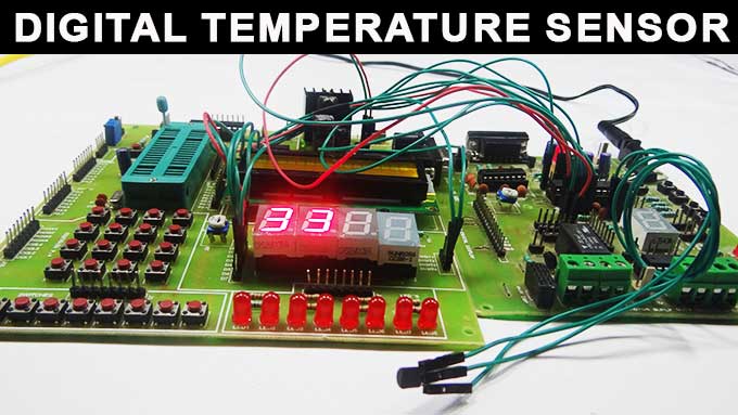
Summary of Digital Temperature Sensor Circuit
This article details a digital temperature sensor circuit using an ATmega8 microcontroller and an LM35 sensor. The system converts the analog temperature output from the LM35 into a digital value via the microcontroller's internal 10-bit ADC, then displays the result on a common cathode seven-segment display. The design leverages the ATmega8's built-in conversion capabilities to simplify interfacing without external ADC chips.
Parts used in the Digital Temperature Sensor Circuit:
- ATmega8 microcontroller
- LM35 temperature sensor
- Seven segment display (common cathode)
- Current limiting resistors
Temperature sensors are widely used in electronic equipments to display the temperature. You can see the digital clock displaying the room temperature value. It is due to the temperature sensor embedded in it. Generally, temperature value is analog. It is converted to digital value and then it is displayed. This article describes the same converting analog value to a digital value.
Digital Temperature Sensor Circuit Principle:
The main principle of this circuit is to display the digital temperature value. Here, ATmega8 microcontroller is used. The ATmega8 has inbuilt analog to digital converter with six multiplexed channels. This reduces interfacing of external analog to digital converter IC. The analog temperature value is directly applied to input ADC channels of microcontroller. Successive approximation method is used for Analog to digital conversion internally.
Digital Temperature Sensor Circuit Design:
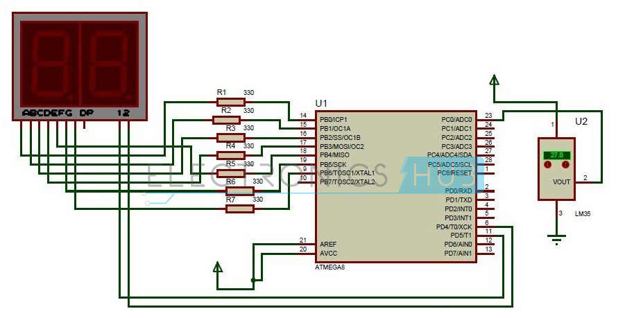
The digital temperature circuit consists of ATmega8 microcontroller, LM35 temperature sensor, 7 segment display. The temperature sensor Lm35 is connected to one of the ADC channels of microcontroller.
ATmega8 has six ADC channels at Port C. PC0-PC5 pins of Atmega8 act as ADC channels. This shows that one can interface six analog values. But only one conversion is done at a time depending on the priority of the input channels. The resolution of ADC is 10 bit. Remember that for conversion Vref and Avcc are externally connected as shown in circuit.
Generally, all the port pins of ATmega8 microcontroller act as normal input /output pins until their special functions are declared. ADC registers inside the controller have to be declared in order make Port C to act as ADC channel.
Lm35 temperature sensor has three terminals. Placing the flat surface towards you first pin is Vcc, Second pin is Output and the third pin is Ground. Output pin of temperature sensor is connected to the first ADC channel i.e. PC0 pin of microcontroller.
Seven segment display has eight pins and one common pin. Leaving Dp, connect all the seven pins to port B. Connect A to PB0, B to PB1,_____, G to PB6. Seven segment display used here is common cathode display. Current limiting resistors were used between controller and the display.
For more detail: Digital Temperature Sensor Circuit
- What is the main principle of this circuit?
The main principle is to display the digital temperature value by converting the analog temperature value to a digital value. - How does the ATmega8 handle analog to digital conversion?
The ATmega8 uses its inbuilt analog to digital converter with six multiplexed channels and employs the successive approximation method internally. - Which pins of the ATmega8 act as ADC channels?
Pins PC0 through PC5 on Port C act as the six available ADC channels for the microcontroller. - How is the LM35 sensor connected to the microcontroller?
The output pin of the LM35 sensor is connected to the first ADC channel, which is the PC0 pin of the microcontroller. - What type of seven segment display is used in this design?
A common cathode seven segment display is used in this circuit design. - How are the seven segment display pins connected to the controller?
All seven pins except Dp are connected to Port B, where A connects to PB0, B to PB1, and G to PB6. - Why are current limiting resistors used in this circuit?
Current limiting resistors are placed between the controller and the display to protect the components. - What resolution does the ADC in the ATmega8 have?
The resolution of the ADC in the ATmega8 microcontroller is 10 bits.