Attendance in colleges is generally paper based which may sometimes cause errors. Taking attendance manually consumes more time. So the proposed attendance system uses RFID technology to take attendance. In this system, each student is issued an RFID tag. Controlling unit is in the institute. Whenever the card is placed near the reader, it will take the attendance. This article explains the same. But, before going to read this post, once get an idea about how to interface LCD with AVR Microcontroller as it is also included in this circuit.
RFID Based Attendance System Circuit Principle:
RFID based attendance system consists of RFID Reader, RFID Tag, LCD display and microcontroller unit. RFID can be interfaced to microcontroller through USART. Data is transferred from RFID cards to reader and from there to microcontroller.
Radio frequency technology is used in many applications. RFID tags are of two types – 1) Passive Tags and 2) Active Tags. Passive tags contain 13 digit number tag inbuilt in it, where as active tag is read/write tag i.e. one can read from the tag and write to the tag. This project uses passive tag. In real time, one can issue active tags to the students, with their roll numbers as their tags. RFID reader contains a copper winding in it. This winding acts as an antenna.
When the tag is placed near the reader, due to the induced mutual inductance energy, data is transferred to reader. Reader then transfers data to the microntroller. Microcontroller checks for the data continuously, if any data is received, microcontroller compares the data in data base. If the tag is authenticated, microcontroller takes the attendance. Also you can check out the rfid based attendance system output video.
Circuit Design of RFID Based Attendance System:
RFID based attendance system has very simple circuit design. The RFID Reader has transmit and receive pins. These pins are connected to the transmit and receive pins of the micro controller i.e. PD0 and PD1 pins of microcontroller.VCC is connected to 5v and GND is connected to ground. If pins are not available to the module, connect it using DB9 connector. PD0 pin is receiver and PD1 pin is transmitter.
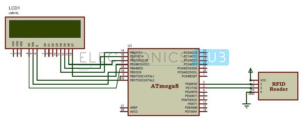
RFID module communicates with the controller using USART, where USART is a communication protocol. USART is acronym for Universal Synchronous and Asynchronous Receive and Transmit. Serial data can be transmitted from RFID module to microcontroller using UART.
For more information: RFID Based Attendance System – Circuit, Working, Source Code