
Summary of Auto Intensity Control of Street Lights
The article describes automating street light intensity to save energy by reducing lumen output during low-traffic or early-morning hours. Two implementations are outlined: one using an ATmega8 and another using a PIC microcontroller. The ATmega8 design uses PWM to vary LED intensity based on calculated peak hours, with inputs from an LDR for ambient light and a DS1307 RTC for time; an LCD displays time and a relay/LED array provide switched high-power LED lighting. I2C is used for RTC communication.
Parts used in the Auto Intensity Control of Street Lights:
- ATmega8 microcontroller
- PIC microcontroller (alternative design)
- DS1307 RTC (Real Time Clock)
- LDR (Light Dependent Resistor)
- LCD (interfaced in 4-bit mode)
- Relay
- High-power LED array
- PWM output pin (microcontroller pin)
- I2C bus lines (SDA and SCL wiring)
- Interfacing resistors and wiring (implied)
treet lights are controlled manually in olden days. These days automation of street lights has emerged. But one can observe that there is no need of high intensity in peak hours i.e. when there is no traffic and even in early mornings. By reducing the intensity in these times, energy can be saved to some extent.
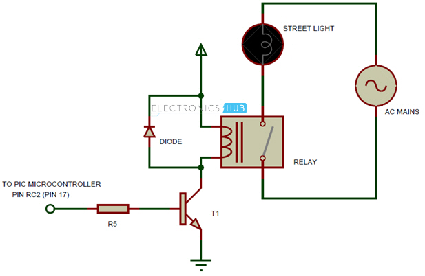
There are many methods to save the power like Switching the street light on detecting vehicle , Street light controlling using LDR and relays etc. The proposed circuits controls street light intensity by calculating the peak hours.Two circuits are shown in this article,one explaining the street light control using ATmega8 and second explains street light controlling using PIC microcontroller. Most commonly found street lights are HID or High Intensity Discharge lamps, which consume a lot of power. In order to save energy, the circuits are designed with high intensity LEDs in place of HID lamps.
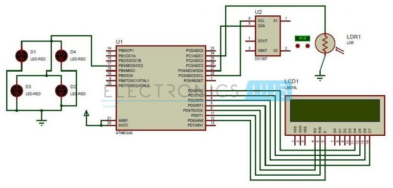
Auto Intensity Control of Street Lights using ATmega8
Circuit Principle
The main principle of this project is to Control the intensity of street lights using PWM.Peak hours of a particular area are calculated and accordingly PWM signal is adjusted by microcontroller to increase or decrease the intensity of street lights.
These peak hours can be calculated by considering parameters like traffic density,time, light intensity of the environment.
Circuit Design
The auto intensity control of street lights circuit is simple but it requires more coding part. This circuit consists of Atmega8 controller, DS1307, LDR, Relay and LEDs.
LDR:LDR is used for calculating the light intensity of the environment .The light dependent resistor is connected to ADC1 (PC1) pin of the micro controller. The analog light value is converted to digital value using ADC.
RTC:Current time is calculated using RTC. Real time clock has 8 pins out of which SCL and SDA are connected to PC5 andPC4 pins respectively. SCL is serial clock while SDA is serial data RTC is I2C compatible, where I2C means inter integrated circuit. One bit of data is transmitted on data bus for each clock cycle.
Data can be transferred between devices, using only two bi-directional buses. Each device can act as a slave or master. The slave devices will have one address and these devices can be accessed using this address.
LCD:LCD is the display used for displaying time which is read from RTC IC. Interfacing of LCD in 4-bit mode is shown in circuit diagram. D4-D7 pins of LCD are connected to PD0-PD3 pins of microcontroller.
RS pin of LCD is connected to PD4 pin of micro controller. RW and Enable pins are connected to PD5 and PD6 pins of controller.
LED array is number of high power LEDs connected in series. It is connected to PWM pin of the microcontroller.
I2C Protocol
I2c is a communication protocol invented by Philips Company. This is well suited for communication between integrated circuits and peripherals. This uses two lines to transfer data.
- Serial Data – SDA
- Serial Clock – SCL.
- This can connect up to 128 devices using two wires. Each device connected will have an address. The device which initiates the data transfer is called Master.
- Every device will have 7 bit address.
- Master initially sends the START bit on the data line.
- Then it sends the address of the device with which wants to communicate and the mode of operation i.e. read or write.
- The slave devices listen to the incoming data and checks if its address matches to the received data. The device whose address matches send an acknowledgement signal.
- Then master starts transmitting or receiving the data from the slave.
- After completion of the transmission, Master sends a STOP bit.
- Data on SDA can be changed only if SCL pin is low.
For more detail: Intensity Control of Street Light
- What is the main principle of the project?
The main principle is to control street light intensity using PWM adjusted by a microcontroller based on calculated peak hours. - Which microcontrollers are used in the article designs?
The article describes designs using ATmega8 and a PIC microcontroller. - How is ambient light measured?
Ambient light is measured using an LDR connected to the microcontroller ADC (ADC1/PC1). - How is current time obtained in the circuit?
Current time is obtained from a DS1307 RTC connected via I2C (SDA to PC4 and SCL to PC5). - How does the microcontroller vary light intensity?
The microcontroller generates a PWM signal to increase or decrease the LED array intensity according to peak hour calculations. - What display is used to show time?
An LCD is used in 4-bit mode to display time read from the RTC. - Why are LEDs used instead of HID lamps?
High-power LEDs are used to save energy compared to high intensity discharge (HID) lamps. - Which pins are used to interface the LCD?
D4-D7 are connected to PD0-PD3, RS to PD4, RW to PD5, and Enable to PD6 of the microcontroller. - What communication protocol does the RTC use?
The RTC uses the I2C communication protocol with SDA and SCL lines.
