Generally, appliances used in our home are controlled with the help of switches. These days, you can see automation of these appliances using many technologies. This article presents the controlling of home appliances using DTMF technology.
DTMF is acronym for Dual Tone Multi Frequency. So, just think when you make call for customer care, they will ask you to press 1, 2 or any other number. When you press a number from your mobile, one particular action is happening. All this is because of DTMF. When a button is pressed in your mobile keypad, it will generate a tone of two frequencies. These tones are called row and column frequencies.
Generally, row frequencies are low frequencies and column frequencies are high frequencies. These frequencies for DTMF are chosen in such a way that they don’t have harmonic relation with the others, so that they will not produce same tones. The column frequencies are slightly louder than the row frequencies to compensate for the high-frequency roll off of voice audio systems.

Related Post: DTMF Controlled Robotic Vehicle without using Microcontroller
We have learned that each button pressed in keypad will produce a tone which differs from others. Now we should use these tones for our appliances. So this DTMF encoder is present in mobile. Output from keypad can be converted into digital form using DTMF decoder IC HT9107B. Interfacing of this IC to MCU is show below.
DTMF Controlled Home Appliances Circuit Principle:
The main principle of this circuit is to control appliances like light and fan using DTMF technology. DTMF encoder is present in your mobile and decoder is HT9107B IC. Mobile jack is connected at 1nf capacitor. Mobile jack consists of two wires (Red and black). Red wire is connected to the decoder IC and Black is grounded. When a button is pressed from mobile it generates a tone which is decoded by the decoder IC and it is sent to ATMEGA8 controller. Controller then checks for input and it produces the output according to the code written to it.
Circuit Components:
This circuit mainly consists of the following components.
- ATmega8 microcontroller U1
- HT9107B IC
- Relay
- AC Load
- Resistors – R1, R2 and R3
- Capacitors – C1, C2, C3 and C4
- Crystal Oscillator X1
Circuit Design of DTMF Controlled Home Appliances:
The decoder IC consists of an inbuilt operational Amplifier. The output of op-amp is given to the pre-filters to separate low and high frequencies. Then it is passed through frequency and code detector circuits, thus 4-bit binary code is latched.
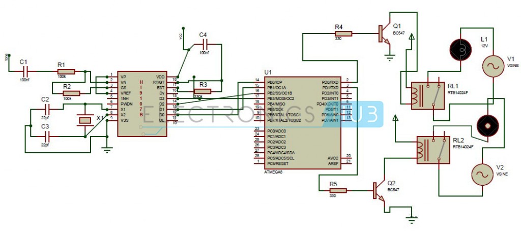 Tone from mobile is sent to op-amp through series of resistor (100 kilo-Ohm) and capacitor (1nf). Pin1 of DTMF IC i.e. non inverting pin is connected to pin4 i.e. Vref. Pin3 is the output of operational amplifier which is feedback to pin2 using 100 kilo-Ohm resistor. 7 and 8 pins are connected to crystal oscillator of frequency 3.579545 MHz. 15th pin is data valid pin it becomes high when DTMF tone is detected else remains low. The process of frequency detection to digitalization of the signal is done by steering circuit consisting of EST, RT/GT, and resistor (10k), capacitor. Pins 11 to 14 produce the decoded output.
Related Post: Mobile Phone Controlled Home Appliances without using Microcontroller
The output pins of DTMF IC (i.e. 11 – 14) are connected to PB0-PB3 pins of controller. Output pins of the controller i.e PD0 and PD1 are connected to relay. Relay output is connected to AC source i.e. light or fan.
Relay acts as a switch. It produces isolation from different parts of the circuit. In our project it is used to switch AC load using 5v which is maximum voltage from controller. Relay used here is magnetic relay.
How to Operate the Circuit?
When the circuit is powered, controller continuously checks the inputs. When ‘1’ is pressed from mobile keypad, decoder IC decodes the tone and produces 1(0001), it is given to microcontroller which in turn produces high output at PD0 pin. PD0 is connected to relay. Relay is used for switching the circuit and thus fan is ON. Similarly, if the received input is 2 fan is switched off. If received input is 3 light is switched on and if it is 4, light is off.
For more detail: DTMF Controlled Home Automation System Circuit