Introduction
We implemented a prototype for a moving alarm clock which runs away from the user when they try to silence the alarm. It has all the features of a “regular” alarm clock: settable time and alarm, snooze, and alarm on/off. The alarm clock displays the time in 24-hour format on a LED seven-segment display. The whole unit is mounted on a chassis with caterpillar-style wheels driven by two small DC motors. A proximity sensor is mounted near the snooze button which is activated whenever the user’s finger nears the button, causing the clock to move away. It is intended to lure the user out of bed when the alarm sounds. Instead of being able to hit snooze three or four times and sleep in, the user will have to get up and chase the clock to silence it.
High-Level Design
The idea of our project rose from a common problem many college students face: ineffective alarm clocks. Regardless of how loud the alarm is, a sleepy college student can easily snooze/turn off the alarm and go back to sleep. To combat this, we wanted to design an alarm clock that would force the user to actually be somewhat alert to turn off the alarm. The end result was an alarm clock that runs away from the user when the user tries to snooze or turn off the alarm.
Logical Structure
At a high level, we split our design into four major subsystems: time calculation and display, alarm tone generation, motion control and proximity sensing. Throughout our design process, we made sure to have concrete interfaces between each of the subsystems such that we could work on different subsystems concurrently and also debug more easily.
While implementing our design, we had to make the decision to use either a hardware or software implementation. We made this decision by considering the factors of simplicity, flexibility, and overall performance. For example, we initially implemented the alarm tone generation in software using pulse-width modulation (PWM) to produce a sawtooth wave output directly from the microcontroller. This would then be fed to a hardware amplifier to drive the speaker. We switched to a hardware implementation when we realized that the hardware oscillator is simpler to build then the amplifier, and can drive the speaker directly. Other portions of our design (such as computing the motor control signal and calculating the time) where much more easily implemented in software with the additional benefit of being very easy to change and debug.
While we did not draw inspiration from similar products for this idea, we later found out that there existed an alarm clock manufactured by NANDA Home (Clocky). It has a similar behavior to our alarm clock, so the patents that exist for this clock would be very relevant to our project should we take our project further. However, a fundamental difference between our design and Clocky is that Clocky moves and hides during the night, before the alarm goes off and then the user has to find it. Our design does not move until the user tries to silence the alarm, and then it moves away from the user.
Hardware Design
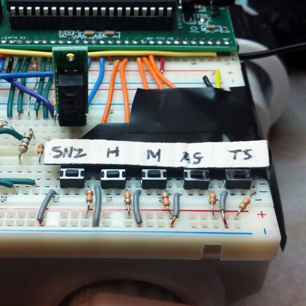
There are four main hardware components to our alarm clock: the inputs to the microcontroller (buttons, switches, and sensors), the seven-segment display, the motor drive system, and the alarm tone oscillator.
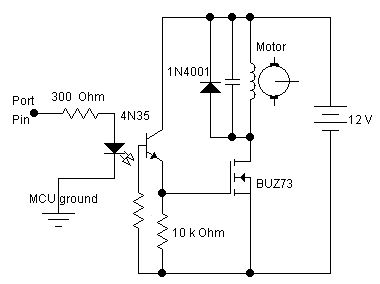
The motors used to drive the alarm clock draw too much power (about 0.5 amp) to be driven directly by the microcontroller. We used a motor control circuit set up so that the microcontroller outputs a digital high or low which acts as a switch, turning on or off the motors. When running, the motors draw their power directly from the 9V battery supply.
Parts List:
| Item | Vendor | Unit Price | Quantity | Cost |
| ATMega 1284p microcontroller | ECE 4760 lab | $5.00 | 1 | $5.00 |
| 7-segment display, 4 digit | Sparkfun | $1.95 | 1 | $1.95 |
| Breadboard | ECE 4760 lab | $6.00 | 2 | $12.00 |
| 1.5W 8 Ohm Speaker | Mouser | $4.03 | 1 | $4.03 |
| Pololu Carrier with Sharp GP2Y0D810Z0F Digital Distance Sensor 10cm | Pololu | $6.95 | 2 | $13.90 |
| 555 Timer IC | ECE 4760 lab | $0.00 | 1 | $0.00 |
| BUZ73 Transistor | ECE 4760 lab | $0.00 | 1 | $0.00 |
| 4N35 Optoisolator | ECE 4760 lab | $0.00 | 1 | $0.00 |
| 1N4001 Diode | ECE 4760 lab | $0.00 | 2 | $0.00 |
| AA Batteries (Sony 8-pack) | The Cornell Store | $1.161/2 ea. | 6 | $4.66 |
| Dagu Rover 5 Tracked Chassis | Pololu | $49.95 | 1 | $49.95 |
| Total Cost | $91.49 |
For more detail: A Moving Alarm Clock Using Atmega1284