Summary of Accelerometer Controlled R/C Vehicle Using Atmega32
This article details the design of an accelerometer-controlled remote vehicle featuring manual and automatic modes. The system uses a steering wheel-shaped remote with an MMA6261Q accelerometer to steer and accelerate via RF transmission, while potentiometers set distance and direction for auto-mode. The car utilizes a digital compass and motor drivers to execute commands. Significant challenges were faced with wireless interference, power supply for the main motor, and H-bridge current delivery, ultimately requiring specific Darlington transistors and a smaller chassis.
Parts used in Accelerometer Controlled R/C Vehicle:
- RCT-433-AS RF Transmitter
- RCR-433-RP RF Receiver
- Atmega32 Microcontroller (2 units)
- MMA6261Q 2-dimensional Accelerometer
- 7404 Inverter Chip
- Servo Motor
- RC Main Motor
- TIP102 and TIP107 Power Darlington Transistors
- H-Bridge Circuit
- 2x16 Liquid Crystal Display (LCD)
- Digital Compass Sensor
- Potentiometers (2 units)
- Pushbutton Switch
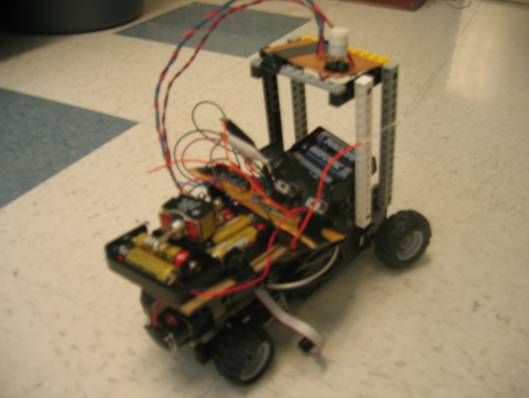
- Lego Car Chassis
- Battery Holders (AA and 9V)
- Optoisolator
- Capacitors (10uF)
INTRODUCTION
In our final design project for ECE 476: Microcontrollers, we decided to build a vehicle controlled, using accelerometers, by a remote control that wirelessly transmits, using RF technology, data to the vehicle to move in any direction. The accelerometers will be mounted on a steering wheel shaped remote control, such that if the user wants to move forward they can lean the steering wheel forward and backward for reverse; to turn left or right they need to turn the steering wheel like steering in an actual car, all in manual mode. In addition there is an automatic mode during which the vehicle goes in the direction requested by the user for the length of the distance requested by the user.
A liquid crystal display (LCD) is located on the remote control and displays the direction, distance and mode (manual or automatic), which is user choice using potentiometers to decide the direction and distance and mode by using a button. We decided on this project because of its ingenuity and similarity to game console systems games, which will appeal to users especially with the ease of use (physically moving the remote control). Additionally, we all love playing with remote controlled vehicles and we wanted to take it to the next step therefore creating an enjoyable form of entertainment for hours.
HIGH-LEVEL DESIGN
One major rationale behind the project was to design a remote controlled car that steers and accelerates by means of an accelerometer instead of a joystick. The accelerometer would be placed on a steering wheel that the user can shift left and right to steer left and right and shift forward and backward to make the car go forward or backward. The more the steering wheel shifts left or right, the more sharply the car turns left or right.
Another major rationale was to allow the user to make the car move a certain distance in a certain direction automatically without having to worry about the difficulties people sometimes have with maneuvering the car accurately. The user can operate two potentiometers: one that determines the direction of the car (NW, N, NE, E, SE, S, SW, W), and another that determines the distance that the car is to travel. When a button is pressed, the car can turn in the proper direction and move to the destination automatically. The user can press this button again to regain manual control.
Remote Controller
The remote controller consists of an Atmega32 microcontroller circuit, an RCT-433-AS RF transmitter, a 7404 inverter, an MMA6261Q 2-dimensional accelerometer, two potentiometers, a pushbutton for toggling between modes and a liquid crystal display (LCD) that shows the command direction, command distance (for the car to travel in automatic mode), and a message stating whether the controller is in manual mode or automatic mode.
When the remote controller is powered, the accelerometer gives two outputs: one for the horizontal (left-right) direction and one for the forward-backward direction. Each output ranges from about 1V to 2V, with 1.5V meaning no shift along that axis. An ADC within the microcontroller converts the outputs to digital signals that are sent to the car through an inverter to the transmitter. In manual mode, the three signals being sent out of the transmitter are an integer for the servo motor (used for steering) that codes for a PWM value; two bits for the main motor (for the wheels) that tell whether the motor moves and its direction of rotation; and the mode (0 for manual, 1 for automatic). The code is programmed so that when the steering wheel is down flat, the car does not move. When the steering wheel is upright, the car moves forward. Steering the wheel left or right will move the car left or right. When the steering wheel is tilted in towards the chest, the car goes backward. The Y output of the accelerometer allows this implementation.
In automatic mode, the three signals being sent are the command direction (represented by an integer from 1 to 8), the traveling distance in feet and the mode number. The mode number is supposed to tell the car what to do with the incoming information.
As the potentiometers are rotated, the LCD update will update the command direction and distance shown. The potentiometer values will not be used until the user presses the button to switch to automatic mode.
Car
The car circuit consists of an Atmega32 circuit, an RCT-433-AS RF receiver, a 7404 inverter chip, a servo motor, a main motor for the wheels and an H bridge for the main motor. The car circuit repeatedly checks for an incoming wireless data packet. When it gets a data packet, it checks the mode, which is the 3rd byte of data in the data packet. The mode number tells the car circuit what to do with the other two bytes of data.
If the mode number is 0, then it means manual mode. The first byte of data is used for determining the direction that the servo motor will direct the car. The second byte of data is used to determine whether the car goes forward, backward or doesnt move at all. The current motion of the car is updated accordingly.
If the mode number is 1, then is means automatic mode. In this mode, the first byte represents the command cardinal direction that the car must move in. The second byte represents the distance in that direction that the car shall move. The servo motor will change the cars direction until the car is facing the desired direction; then the car will continue in that direction until it has traveled the whole distance. While the car is traveling, it does not accept any inputs from the accelerometer. If the user decides to switch back to manual mode, then the car will immediately start to move according to the accelerometer values regardless of whether it reaches its final destination in automatic mode.
PROGRAM DETAILS
Remote Controller Program Details
When the remote controller is turned on, it is initialized to manual mode. In manual mode, the first step is to collect information from the accelerometer. The accelerometer outputs are fed through the analog to digital converter (ADC). The voltage reference chosen was AVcc with an external capacitor at the AREF pin. The ADC output is left adjusted so that the ADCH register gives sufficient information. The analog channel selection bits are used to determine which channel is taking the ADC input for a given conversion. Each accelerometer output has its own ADC input channel.
The signal to be sent to the servo motor is further discretized into 5 basic directions so that the servo motor does not get too shaky. Thus, the ADC output is split up into 5 ranges where each yields a different PWM value for the servo motor. The numerical value sent to the car is a number from 0 to 4 where 0 codes for the highest OCR0 value and 4 codes for the lowest. A lookup table of OCR0 values is used to do this without if-then statements.
The signal to be sent to the main motor is discretized into 3 possible values: backward, forward, not moving. Thus the ADC output range is divided into 3 ranges. For the lowest range, pins 1 and 0 of PORTB are set to 00. For the next lowest range, they are set to 11, meaning go forward. For the highest range, they are set to 01 meaning go backward. There is a small transition range in between the forward and reverse ranges that yields 00.
Even in manual mode, the command direction and command distance are updated so that the user can switch the car to auto mode and make the car start moving the specified distance and direction at any time. The command direction and distance each come from a potentiometer that is fed through two other channels of the ADC. Since there are 8 different command directions, the ADC for command direction is divided into 8 ranges where the lowest range represents North, the second lowest Northeast, and so on. The ADC output for distance goes through no conversion; therefore, distance is allowed to vary from 0 to 255 feet.
An LCD update function updates the information on the LCD about command direction and command distance. The ADC for the command direction is converted to a number from 1 to 8, then the LCD update function uses a case statement to print it out as the appropriate cardinal direction.
The signal is transmitted via Meghan Desais wireless protocol. A special function that we put together, send_data, inputs three data values and uses the wireless protocol function, tx_me, to transmit the signal. Within this send_data function, the individual input parameters are assembled into a character string of length 3 and inputted into the tx_me function.
In manual mode, the send_data function sends out the servo motor PWM, main motor signal, and mode number, which is 0. During each iteration of the endless while loop, a button is checked to see if it has been pressed. When the button is pressed, a short circuit forms between the two port pins that the button is connected to. Detection of a short signals the program to enter the debounce state machine. The debounce state machine prevents one push from being misinterpreted as multiple pushes due to inherent bounciness in the button.
The debounce state machine has 4 states. In state 1, the button has not been pressed at all. When the program detects a short, the debounce function increments the pushstate to state 2, meaning maybe push. When another short is detected, the pushstate is incremented to state 3, meaning pushed. Here, a pushflag is set. Setting of the pushflag signals the program to change modes. If in mode 0, it changes to mode 1. If in mode 1, it changes to mode 0. When an open circuit is detected again, the pushstate goes to state 4, meaning maybe no push. Here, a timer is initialized to 30 and is decremented every millisecond in a compare interrupt. This allows 30 ms before a short is detected again, allowing the button to bounce.
In automatic mode, different data values are sent over. These values are the command direction (numbered 1 to 8), the command distance (numbered 0 to 255) and mode number, which is 1. These values are continuously sent until the button is pushed again. In automatic mode, the car turns into the command direction and moves to its destination. Once in its destination, it will stay until the user switches back to manual mode.
Car Circuit Program Details
The main code for the car initializes everything, then runs on an endless while loop. The action of the main motor is represented by pins 0 and 1 of PORTB. Pin 0 represents reverse direction. Pin 1 represents forward direction. For the car to not move, both pins are set to 0. Because of how they are being used, these pins are configured as output.
The servo motor is connected to pin 3 of PORTB, which is the output compare value of the pulse width modulator (PWM). Timer0 is configured as fast PWM, prescaled by 1024, and the output compare pin is cleared on a compare match. OCR0 is varied to control the direction that the servo motor moves the car. Because varying OCR0 at high resolution makes the servo motor too shaky, we discretized the OCR0 values so that OCR0 could be only 1 of 5 possible values. These values are in a lookup table called servo_array. The lookup table would eliminate the need for if-then statements when determining the OCR0 value. The specific OCR0 values chosen for the servo_array were calibrated by varying OCR0 and looking at how far the servo motor turns with each value of OCR0. We found that OCR0 going from 10 to 40 covered the extremes in servo motor angular position.
Pin 0 of PORTD is configured as an input so that it can receive the RF signal.
The compass is connected to pins 3-6 of PORTD, which are configured as inputs. The compass is, by design, divided into 8 cardinal directions. When the direction is N, S, E, or W, two of the output pins read high and two read low. When the direction is NW, NE, SW, or SE, three of the output pins read high. A separate function in another c file called get_direction checks the pin values in PORTD and uses a series of nested if-then-else statements to determine which cardinal direction is being represented. It is okay to assign each cardinal direction to an arbitrary combination of PORTD pin values because the compass can be placed on the car in such a direction that when the compass reads north the car is actually facing north. For the purpose of easier program design, the cardinal directions are numbered 1 to 8 where 1=N, 2=NE,,8=NW.
The main function first calls the initialization function, then goes into an endless while loop. For each iteration of the while loop, it constantly checks for a new input packet of wireless data. An if statement is used to give separate sets of instructions to the car in manual mode versus automatic mode. In manual mode, the first byte of the data packet is used to index the lookup table of OCR0 values to update OCR0 for the servo motor. The second data packet is used to determine whether the motor goes forward, backward or doesnt move at all. Here, an if-then statement is used to set the pins of PORTB accordingly. If the last two bits of the second RF input byte is 01, it means 0 for forward and 1 for backward. If they are 10, it means 1 for forward and 0 for backward. If it is 00, it means 0 for forward and 0 for backward, meaning dont move. An input of 11 should never be encountered. If encountered, then no statements in the if-then-else statement will be met and the activity of the main motor will not change.
When the 3rd received byte of data is a 1, the program stops entering the code for mode = 0, and enters the code instructions for mode = 1. The first time this set of instructions is executed, the motor is set to move forward and a timer is initialized to keep track of how much time the car has been moving so far. The total travel time for the car is a function of the second byte of wireless input data (command distance) and the measured speed of the car. After the timer and main motor are started, a variable, start, is set to 0, meaning that the next time this set of instructions executes, it will no longer be the first time of execution. The variable, start, is reinitialized back to 1 in the mode 0 instructions.
In the remainder of the instructions for automatic mode, the program determines how far away the current direction is from the command direction. First the get_direction function is used to obtain the current direction that the car is facing based on the values of the PORTD pins. The results are stored in current_dir and stored in a temporary variable called temp. Temp is incremented in a while loop until it matches the command direction. Each increment makes temp go 45 degrees clockwise or to the right. If temp has to be incremented more than 4 times, it means that the car can more easily match the command direction by turning left. An if-then-else statement is used to set OCR0 so that the car turns in the desired direction or remains going straight if the current direction is close enough (within 45 degrees) of the command direction.
The timer is incremented in a compare interrupt that is set to 1 millisecond timebase (prescaled by 64, OCR2 = 250). If we know the cars speed in miles per hour, we can multiply by 5280 to get feet per hour and divide by 3600 to get feet per second. To get milliseconds, we multiply by 1000. This will give a conversion factor of 1/[speed(mph)/3600*5280]*1000 that the command distance is multiplied by to get the travel time in milliseconds.
When the timer variable, t, reaches the value of travel_time, the motor is turned off (PORTB.1,0 = 00). If per chance the command distance is so short that the car travels the command distance before reaching the command direction, then the car will also be required to face the command direction before the main motor turns off. Once the main motor is turned off, the program will enter a while loop that executes until the mode changes back to mode 0.
Even when the cars motor has not turned off yet, the program still constantly checks for incoming data packets during each iteration to check for changes back to mode 0. If the mode changes back to 0, then the instructions for mode = 0 are executed once again. To the user, this means he/she has regained manual control of the car despite whether the car ever traveled the whole command distance. This will keep the user from accidently sending the car off a cliff or something by making command distance too large.
It is possible for the car circuit to be powered when the remote controller is not. In this case, the car will receive no input packet instructions. Certain variables must be initialized in case there is no RF reception. Mode is initialized to 0, the servo motor OCR0 value is set to its middle value so that the servo motor makes the car face forward. The PORTB pins 0 and 1 are both set to 0 so that the car is stationary. Command distance is set to 0.
At some point, the user may turn off the remote controller when the car is still on. The prevent the car from moving indefinitely, the cars motor is automatically turned off after 2 seconds of no incoming data packets. This is done with a variable t_stop, which keeps track of the amount of time passed since a data packet from the remote was received. When the get_data function detects a data packet with the correct ID value, t_stop is initialized to 0. From there, it is incremented in the timer2 compare interrupt, which goes every millisecond. When a data packet comes in that is the wrong ID (interference), the command variables (command direction and command for the motor) are set so that the car faces straight forward and the motor turns off.
Wireless Protocol Functions
txrx_init(tx,rx,baud rate,led): initializes the UART control register to specify whether the circuit is transmitting (tx), receiving (rx) or both. Also initializes the baud rate control register to give the inputted baud rate.
tx_me(data,data_length,tx_id): transmits a characters string, data, of length data_length that has a transmit ID tx_id. tx_id is an ID number that represents from which transmitter the data packet came. This is useful for when more than one transmitter is being used or when other people present are using transmitters.
DecodeOne(msbyte): uses a lookup table to find the true transmit ID associated with the numerical value presented in the received packet
rx_reset(): Sets up the system to wait for another incoming data packet
tx_done(): returns 1 when the transmission is complete; 0 otherwise
rx_done(): returns 1 when a data packet has been received; 0 otherwise
init_getrx(): initializes the current index value to 0 for when the data packet is being read
get_next_rx_data(): gets the next char value in the received data packet. Index value is incremented
HARDWARE DETAILS
Remote Controller Hardware Details
The remote controller circuitry is mounted onto a steering wheel. The Atmega32 circuit, accelerometer, inverter chip, potentiometers, transmitter and LCD are all powered by a 5V power supply. The accelerometer outputs are each connected to a pin of PORTA. Each potentiometer (for command direction and command distance) is connected to another pin of PORTA. PORTA is the port that has the ADC inputs and is configured as all inputs.
Pin 1 of PORTD is used to output the signals that are to be transmittedD through the RF transmitter. Meghans wireless protocol requires that an inverter be placed between the MCU and RF transmitter. Therefore, pin 1 of PORTD is connected to one of the inputs of the inverter chip. The output goes to the transmitter.
The RF transmitter has 4 leads: one power, one ground, one input and one antenna. Meghan Desais wireless protocol specs require that the antenna by wavelength long. The RF transmitter is 433 MHz. The speed of light in meters per second divided by 433X10^6, then divided by 4 yields a length of about 8 inches.
The LCD has 14 pins. The first two pins are connected to ground and power. Seven of the other pins are connected to PORTC. PORTC must therefore be configured as all outputs. We include a header file, lcd.h, that allows us to easily write text to the display with simple functions. According to the specs of this header file, pins 7-10 are disconnected while the other pins are connected to a port, preferably PORTC. Pin 3 of PORTC is also disconnected.
Car Circuit Hardware Details
The Atmega32 circuit, receiver, inverter chip and compass are all powered by the same 5V power supply. The servo motor runs off of a 3.7V power supply, but must still be grounded from the same ground as the MCU. The main motor runs off a separate power supply all together. An optoisolator protects the rest of the circuit from the noise of the main motor. An H bridge is used to channel a sufficient amount of current into the motor in either direction to allow the motor to rotate in either direction. A 10uF capacitor is used to filter out noise on the power line due to the two motors.
The RF receiver has 8 leads. The first lead is the antenna, which like the transmitter must be wavelength long. Pins 2,3,8 are grounded and pins 4,5 are powered. Pin 6 is the analog output, which is not used. Pin 7 is the digital output, and is connected to pin 0 of PORTD through an inverter. This inverter inverts the signal back to what it was when it was outputted from pin 1 of PORTD on the remote controller.
The servo motor has 3 leads: power, ground and signal. The signal lead is connected to pin 3 of PORTB where it is fed the PWM signal whose duty cycle determines the angular position. The servo motor was assembled into the Lego car in such a way that when it makes a complete rotation, the wheels turns from all the way left to all the way right.
Difficulties and Tradeoffs
One major source of difficulty was the wireless transmission. One of the first obstacles was in trying to use a demo code that was designed for a 4×40 LCD as opposed to the 4×16 LCD that we had. Because a 4×40 LED is so much longer, we were unable to see the complete payload. We also realized that inverters needed to be placed between the MCU and each RF component. Even after we got the demo code to work successfully, the wireless transmission system was finicky. Sometimes it worked and sometimes it mysteriously stopped working even when virtually nothing was changed.
Another tricky part was working the wireless protocol demo code into our code. We found difficulty in transitioning from using the wireless protocol functions in the demo code to using them in our code. Sometimes we would have to start at the demo code and modify it until it resembled our code. There was some challenge to figuring out how much of the demo code was necessary for our code and how much of it was not. In other words, we really needed to have an understanding of what each part of the demo code did. For example, at one point we discovered this line in the demo code that was necessary to determine whether the device transmits or receives.
There were additional challenges to debugging when we were seated near other people who also were using 433 MHz RF. Sometimes we would get random numbers. It was often unclear whether transmission was due to interference or the system not working. At one point there were people nearby transmitting in GHz. Our data never showed up on the LCD then because we were receiving their data at a much higher rate. We also seemed to get interference from other sources of wireless transmissions, such as laptops and Wi-Fi routers. We are not completely sure about it, but our hypothesis is based on that fact that project would work perfectly in areas without any wireless traffic and would always stop working in places high in traffic, and additionally Professor Belina suggested that Wi-Fi would interfere with our transmissions. Additionally, we had another problem that whenever we lost transmission due to interference or anything like that our chip would completely shut off until we either reset it or completely reload the program back onto the chip.
When we tried to achieve bidirectional transmission, we ran into even more difficulties. We figured that if we programmed the Atmega to alternate between transmit and receive mode every so many times a second, then one direction of transmission could be achieved at a time. We found during testing that when we got a block of code to receive successfully, then added another block of code to transmit a few times a second, that the receiver would just stop receiving. This is a problem because we want to remote controller to constantly send accelerometer data to the car to move it adequately without having to allow long periods of time in between to receive data for the cars speed and direction. If the remote controller needs a large block of time to adequately receive a data packet from the car, then the user would not be able to alter the motion of the car very quickly. It would only cause frustration to the user, only for the purpose of giving the user information about the cars motion that he/she may not even care about.
We found out the hard way that the wireless protocol system that we were using was insufficient for the fast bidirectional communication that we wanted for a playable remote controlled car.
Another major source of difficulty was in the main motor. We had tremendous difficulty in getting the proper power supply (voltage and current) to the motor. We could not power the motor adequately off the proto board because it did not deliver the proper amount of current. When we used this other power supply, the motor started to get overpowered.
When we finally did get the main motor to rotate, we found that when we touched it slightly it would stop rotating. Not only that, it needed a push just to get rotating again. When we got a more powerful motor, we found that the Lego car that we built was far too heavy even for the powerful RC motor we found. We had to make a smaller less impressive looks car without all the fancy shocks and gears we had before. Even then the car barely moved when we put it onto the floor.
It also took hours to get the H Bridge to draw the right amount of current. This was extremely difficult to figure out the reasoning behind why this was not working. We tried many basic H Bridge designs from many websites trying to get the motor to start moving. However, every single design we tried never seemed to draw enough current or enough voltage and sometimes both were lacking. As a result, we decided to try having more and more complex circuits with higher gain power transistors such as the TIP 31 and TIP 32. This did not work as well even though these transistors were rated at around 4 Amps they still would not draw more than 1.5 Amps, which our motor needed. Then we decided that we could try and pull more current and add some gain using a Darlington setup with two transistors together, which did not come close to working. On our second to last attempt, we tried hooking up power MOSFET transistors, while this did get the motor moving it was definitely not enough power or torque to get the vehicle moving on the ground with the friction. Finally, we tried the power Darlington transistors TIP102 and TIP107 and using a simple H bridge circuit shown in the appendix, we were able to get the motor to move as fast as possible with the power and amount of weight on the vehicle.
It was hard to get the compass successfully hooked up right because all the pins were arranged in a circle instead of straight lines. The power pins and ground pins were all spread out. Each power pin and ground pin was connected to power and ground via a separate wire on a little board. By the time all the power pins, ground pins and signal pins were hooked up, the board was a big mess of solder at the bottom. This solder mess could explain why we took awhile to get one of the pins on the compass to work. We found the soldering problem when we checked the circuit for unwanted shorts. We found that one of the signal pins was shorted to ground and we fixed it.
TESTING METHODS
The LCD was a key part in testing. Instead of printing onto the hyperterminal, we used the LCD. When something did not print on the LCD when it was supposed to, we would toggle the LED in a certain part of the code in the while loop to see if that part of the code is executed repeatedly.
On the remote side, we printed out the accelerometer outputs to ensure that the accelerometer was successfully sending in data. On the car side we also used an LCD to monitor the effectiveness of wireless transmission. One thing we commonly did was print out the wirelessly transmitted data in its raw form. The next step would be to print it out in its more final form (i.e. cardinal direction in letters instead of integers).
We used the LCD demo code frequently because sometimes nothing would print on the LCD. We also used the wireless protocol demo code frequently because wireless transmission frequently stopped working.
In manual mode, we would transmit the number from 0 to 4 representing the discretized accelerometer X values, and a number 0 to 2 represent the three possible values for the main motor. These two values are critical in controlling the car manually.
In auto mode it was a little more complicated. We printed the actual direction next to the command direction sent from the remote. We also printed out OCR0 to make sure that OCR0 makes the car turn left or right depending on the relationship between command and actual direction. We also would print run onto the LCD to mean that the cars motor is currently running. All of this allowed us to debug without having to connect to any motors.
For the motor we tested it by connecting the motor to batteries and seeing whether it would run with the amount of power supplied, current and voltage respectively. Additionally, to test the H Bridge all those numerous times, we used the power from either batteries or the protoboard on the ECE 476 benches and then using the oscilloscope we measured the voltage outputted out of the terminals. This was effective at first but then when we connected the motor to the terminals we could never get it to turn on because of the lack of current, so this became the new standard of measuring whether an H Bridge was effective, which was connecting a motor to the H Bridge and see if it was enough power.
RESULTS
Data is transmitted from the remote controller to the car at about 4 times per second. Therefore in manual mode, the direction of the car is updated at about 4 Hz. Because of the shakiness of the servo motor, the direction of the car cannot be chosen by the user to a very high accuracy. The direction is only discretized into 5 possibilities.
Because of difficulties in just getting the motor to move, we decided it would be too much to ask for the user to determine the direction of the main motor with the accelerometer. Instead, we decided to only determine whether the motor moves at all and in what direction.
The user also can only determine the command direction to a limited accuracy because the compass only has 8 cardinal directions on it. For instance, the user cannot choose a command direction halfway between NW and W. Therefore, the maximum discrepancy between the desired command direction and the closest possible command direction is 22.5 degrees.
The whole system is fairly playable aside from the unreliability of the main motor. The user simply turns on the remote control and the car. The default starting point is manual mode, which is how users usually operate remote controlled cars. The user can steer the wheel left or right and the car will move left or right. A simple turn of the knobs on the steering wheel allows the user to adjust the command direction and command distance. A push of the button sends the car off. An additional push of the button stops the car from moving on its own.
The safety considerations are fairly minimal. The biggest concern we can think of is what may happen if the equipment got soaked with water. Perhaps there may be a risk of the holder of the remote getting electrocuted. As such, we would recommend placing a clear warning on the car and remote controller that the device should be kept dry at all times. In addition, we think that the circuitry should be covered preferably by an insulator to prevent the user from touching the inner circuitry, which may get pretty hot.
CONCLUSION
We had experienced much more difficulty than we had anticipated. Overall, we thought that the whole project seemed straight forward, but there were many complications from the unreliability of wireless reception to power supply problems with the main motor. We thought that we were going to have a nice big fancy Lego car with shocks and huge gears (10:1 gear ratio) moving at 25 mph possibly. Instead we found surprising difficulty just getting the motor to move at all, more difficulty in getting it to move the wheels with the gears and even more difficulty getting the car to move when it was placed on the ground. We had to make many adjustments, particularly to the motor we were using and to the design of the Lego car. The Lego car had to reduce in size dramatically so the RC motor could move it. The RC motor, which can go up to 25 mph, had to be cleaned out. There still was difficulty after it was cleaned out. Now instead of the big robust fast-moving car we pictured, we have a little car with 3:1 gear ratio that moves a little if we are lucky.
We also needed to make adjustments with how the servo motor was controlled so that it would not be so shaky. As a result, we did not get that nice continuous control of direction by the user that we had expected. We also could not allow the user to continuously control the speed with the accelerometer as we had thought we could because it was so hard just to get the motor to move the car at all.
For awhile we went around in circles, but once we committed to unidirectional transmission alone, there was progress to a working product. The steering wheel was able to control the cars wheels nicely. We decided to make it so that when the user places the steering wheel down, the wheels dont move. The wheels only move forward when the steering wheel is upright and backward when the steering wheel is tilted inwards. We conclude that it would be a better use of any persons time who wants to use RF wireless technology to write their own protocol because it would have taken less time to do that and would have had the ability to be bidirectional. Additionally, we would like to point out that the best H Bridge to use for an RC motor is the one we ended up with, using Darlington BJTs instead of trying to deal with other circuits shown on other websites. However, finally we managed to get everything to work well together and the vehicle moves effectively in the manual and automatic modes, using the digital compass well.
Intellectual Property
We used the wireless protocol written and designed by Meghan Desai. The RF transmitter and receiver circuits also were designed by a corporation from which we bought the circuits. We also based our custom PC board on Bruce Lands design that is shown on the ECE 476 website. Finally, the H Bridge was borrowed from one of the TAs that was in the class last year, Tytus Mak and Daniel DiBernardo, and was the most effective.
RF Frequency Laws and Safety Regulations

In our robotic vehicle design project, we will need to take a few safety issues into consideration. Firstly is the controller for the robotic vehicle, which will be manipulating the vehicle wirelessly. We will be using an RF (radio frequency) protocol that will follow all safety regulations instituted by ANSI and IEEE for using such wireless technologies without affecting humans at all since the FCC does not mandate any federal regulations as of yet and recommends using these as the federal standards. This will be done by limiting the frequency between 100-300 MHz and using 0.1-0.4 W/kg as stated by ANSI and the IEEE, which is done by using the protocol suggested by Meghan Desai.
Parts List:
| Part Number | Supplier | Quantity | Unit Price |
| RCT-433-AS | Bruce Land | 1 | $4 |
| RCR-433-RP | Bruce Land | 1 | $4 |
| Atmega32 chip | Avnet | 2 | $0 |
| 1490 Digital Sensor | Dinsmore Sensor | 1 | $15 |
| 3904 BJT | Bruce Land | 4 | $0.50 |
| AA battery | Target | 9 | $0.42 |
| 9V battery | Target | 2 | $2 |
| Button | Bruce Land | 1 | $0.50 |
| Servo motor | Jack Logue | 1 | $0 |
| Lego Car | Jack Logue | 1 | $0 |
| RC motor | Providence Hobbies | 1 | $15 |
| 2×16 LCD | Newhaven Display | 1 | $0 |
| Hose | Lowe�s | 1 | $2.00 |
| Valve | Lowe�s | 1 | $1.26 |
| Wood | Lowe�s | 1 | $1.50 |
| Small solder board | Bruce Land | 5 | $1 |
| TIP102 and TIP107 | Jack Logue | 4 | $0 |
| MMA6261Q | Freescale Semiconductor | 1 | $0 |
| Header socket plug | Bruce Land | 102 pins | $0.05/pin |
| Potentiometer | Jack Logue | 2 | $0 |
| 2AA Battery Holder | RadioShack | 1 | $1.50 |
| 4AA Battery Holder | RadioShack | 1 | $2.00 |
| 4AA Battery Holder | Varun Pattani | 1 | $0 |
| Custom PC Board | Bruce Land | 2 | $5 |
| DIP Socket | Bruce Land | 4 | $0.50 |
| Total Cost | $75.63 (63 cents over) |
For more detail: Accelerometer Controlled R/C Vehicle Using Atmega32
-
How does the user control the vehicle manually?
The user leans a steering wheel forward or backward to move the car and turns it left or right to steer, utilizing an accelerometer mounted on the wheel. -
Can the vehicle move automatically without constant input?
Yes, in automatic mode, the car moves in a specified cardinal direction for a user-defined distance until the destination is reached or manual control is regained. -
What technology transmits data between the remote and the car?
Data is transmitted wirelessly using RF technology at 433 MHz via an RCT-433-AS transmitter and receiver pair. -
How many directions can the automatic mode command?
The system supports eight cardinal directions represented by integers from 1 to 8, including North, Northeast, East, Southeast, South, Southwest, West, and Northwest. -
What happens if the remote controller loses connection with the car?
If no data packets are received for two seconds, the car's main motor automatically turns off to prevent indefinite movement. -
Why was the Lego car chassis size reduced?
The original chassis was too heavy for the available motor torque, so it was made smaller to ensure the vehicle could move effectively on the ground. -
Which components were used to solve the high current requirement for the motor?
The team utilized TIP102 and TIP107 Power Darlington transistors within an H-bridge circuit to draw sufficient current for the main motor. -
Does the system support bidirectional communication?
No, the final design only supports unidirectional transmission from the remote to the car due to difficulties with the wireless protocol and interference.