Introduction and High Level Design
Our project was to design a two degree-of-freedom stationary helicopter, autonomously controlled by an evolving neural network. A normal helicopter has six degrees of freedom, which makes any form of control exceptionally hard, let alone autonomous control. What our design does is limit the movement of our system to just two degrees-of-freedom, up and down, and side to side which lets it rotate around the center, while at all times keeping the system rigid in the other four degrees-of-freedom.
Our final project was not our original goal. The evolution of our project design was an adventure in itself. Originally, we planned to design a triangular helicopter. The concept was to put the microcontroller in the center of a triangular structure, and attach motors at each of the three points. The motors would all have propeller blades attached to them, and would spin at the same speed, creating lift, and raising the helicopter. The structure would move in any of the three directions by lowering the speed of the motor at that corner, causing that point to dip downwards, and letting the other two motors propel the device forwards. Movement in each of the three directions would be controlled manually by pressing buttons on a remote-control. After analyzing the mechanical issues of this design, and speaking to a few professors, we decided to change our plan. We were told that there would be problems with unbalanced torque, which would cause the whole ! structure to spin, and would make our control system much more complicated than we had expected.
With this information, we decided to design a quad-copter instead, which would consist of two sets of counter-rotating propellers. We hoped this would eliminate the issue of unbalanced torque in the system, and still let movement be possible by lowering the speed of two motors simultaneously. Controlling motion this way would cause one side of the system to dip, creating the unbalanced lifting forces that cause motion, but still keeping the torques balanced. Unfortunately, after talking to various Professors and analyzing the control scheme that would be required to keep the system stable, we again reached the conclusion that this project was too much for us in this timeframe. We would not have enough time to implement a sufficient control scheme, and our budget was not large enough to allow us to purchase four sets of motors and propeller blades that would be strong yet light enough to create sufficient lift, while still also allowing us money for other c! omponents like the microcontroller itself and various sensors.
After changing our ideas twice, we talked with Professor Land about the feasibility of our ideas, and what we could do instead. We still hoped to design something that could fly. After some brainstorming, we came up with what became our final idea: the two degree-of-freedom learning helicopter, controlled by an evolutionary neural network. Restricting the movement of the helicopter by attaching it to an arm eliminates the need to stabilize a true hovering device, making the hardware much simpler, and the neural network learns how to best control itself, thereby replacing the need for a traditional PID controller.
Hardware
The hardware aspect of this project was a mix of mechanical construction and electrical components. In the structure aspect, we needed a large and stable base, but also a light yet strong arm to support our motors. On the electrical side, the hardware was very similar to that which was used in Lab 5.
First and foremost, we needed to find a strong, yet affordable motor and propeller blade combination. This is actually the main reason that our original ideas were deemed not feasible for this project. After consulting two professors in the Mechanical and Aerospace Engineering Department, it was determined that motors that were strong and light would not be cheap enough for the budget constraints we had, since we would have required three motors for our first idea, and four for our second idea. Once we switched to the armed structure, however, we had more leeway in the weight and cost aspects of our motors. After researching how RC helicopters work and testing various motors and propeller blades from destroyed toys, we were referred to a group which did a similar project in 2004. Their project was a stationary, one degree-of-freedom helicopter that was controlled by a classical PID controller. What was of more interest to us, however, was their physical setup. They achieved their goal by using a standard DC motor from RadioShack with a simple, 2 blade propeller attached directly to the motor shaft. This was considerably simpler than the systems we had thought of implementing, which would have required a gearing system to provide greater torque to the propeller. Based on the success of their project 4 years ago, we decided to use the same motor and propeller blade setup. We purchased similar motors from RadioShack and ordered the propeller blades online from HobbyLobby.com.
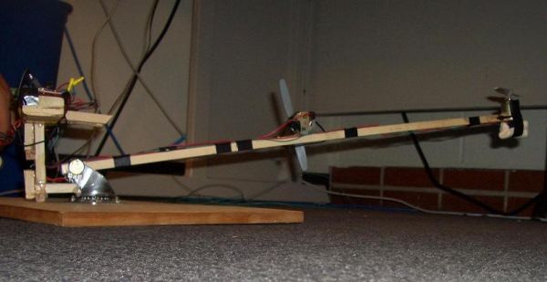
We then had to figure out the physical construction of the system. We needed a base large enough to hold our components, and heavy enough to remain in place while the helicopter ran, and we needed a setup which would allow the system to have to have two degrees-of-freedom. The base was simple enough – we used a large piece of scrap wood provided to us by Professor Land. Creating the rotating arm required some creative thought. After coming up with the idea of attaching some kind of hinge joint to a rotating disk, we went to Lowes to purchase the necessary parts. While there, we spoke to an Lowes employee and received some help as to how to go about doing our construction. He pointed us to a rotating caster which actually took care of both the hinge and the rotation. A rotating caster is what is generally used to hold each wheel on the bottoms of swivel-chairs, or other wheeled equipment. We removed the wheel from the caster, and the remaining structure was perfect for our project. From here, we just had to screw the caster onto the base, and add the arm.
Next, we had to start playing around with different combinations of wood, motors, and propeller blades in order to find the best configuration for the structure. The most critical part was having a sturdy arm that would survive a large amount of testing and would not buckle under the weight of the motor attachet to the end. At first, we tried using some scrap maple that was provided to us by Professor Land. Unfortunately, even though this wood was very sturdy, it proved to be much too heavy; the motor could not lift itself and the arm together. We then went back to Lowes to search for lighter wood. Lowes provided us with several peices of scrap wood free of charge. Unfortunately, this wood also was not a success. The scrap wood from Lowes proved to be both too wide for the caster, and still too heavy for the motor to lift. It was at this point that we went to the Cornell Store on campus and purchased a long stick of bass wood. This wood is very light, like balsa wood, but still has enough stiffness to provide a stable arm. The only issue was that the piece was very thin, and would slide back and forth from one side of the caster to the other. We fixed this by cutting off two small pieces and gluing them to either side of where the arm connected to the caster. This made the width perfect, and we moved on to working on the actual joint structure.
We knew that the arm had to be able to swing freely around the joint in the caster, but we also needed a way of determining the angle that the arm was at relative to ground. Our initial thoughts were to attach an accelerometer to the arm and simply to use the metal shaft that comes with the caster to provide a joint to swing around. We worked with the accelerometer until one of the TAs suggested we try using a potentiometer in the joint, since the accelerometer did not seem to have the speed and accuracy we required. After some initial testing with a potentiometer we found in the lab, we ordered some of our own to use in the joint. This method turned out to be perfect for our needs, as we were able squeeze the potentiometer knob into the wood so that as the arm rose, it would twist the potentiometer knob with it. We used two potentiometers to connect the arm to the caster, so as to keep the design symmetric and well-balanced, but we only used one for our data input. The other remained unconnected.
At this point, all that remained in the physical structure was to actually secure the motors. We did this by gluing the motors to the wood, and then securing them further using cable ties. This was to ensure that the motors would not be able to move during operation. One of the TAs then pointed out that all our wires would get tangled up when the structure spun around the caster. We realized that we needed to mount the electrical hardwareso that it would rotate with the arm. We took care of this by using some of the scrap wood from Lowes that we had not used. We cut it down to fit into the caster and stick up behind it in a T-shape. The stand structure is connected to the sides of the caster, and is secured by massive amounts of hot glue. The electrical components are mounted on top of it.
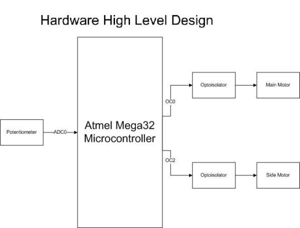
As mentioned earlier, the electrical hardware was very similar to the hardware created for Lab 5, which was a Digital Thermometer with a fan. The part of interest to us was the fan side of the hardware, since the fan used in that lab was essentially a DC motor, and functioned similarly to the motors we planned to use for this project. The motors, like the fan in Lab 5, required optoisolator circuits to protect the microcontroller circuit from the high-voltage power supply. This was especially important since each motor runs on a 19V supply, and pulls 1.6A of current when running, and the microcontroller must be protected from any back-EMF generated by the motor while it switches on and off. To provide power to the motors, we used Matt’s 19V laptop power supply. We constructed two optoisolator circuits, like the ones from Lab 5, on small solder boards and mounted them to each end of our hardware stand. The schematic for these circuits, as well as the pin outs for the various components of the circuits, can be seen in Appendix 2. The only notable change we made to the original Lab 5 circuit shown in this schematic, was to completely disconnect the base connection of the BJT in the optoisolator chip (Pin 6) from the rest of the circuit. This essentially creates infinite resistance for the resistor that does not have a value marked in the schematic.
Parts List:
| Item | Cost per Item | Number of Items | Total Cost |
|---|---|---|---|
| $29.36 | |||
| Potentiometers | $0.50 | 2 | $1.00 |
| Motors | $3.99 | 2 | $7.98 |
| Small Solder Boards | $1.00 | 2 | $2.00 |
| Custom PC Board | $5.00 | 1 | $5.00 |
| Swivel Caster | $4.38 | 1 | $4.38 |
| Propeller Blades | $3.20 | 2 | $6.40 |
| Headers for Optoisolator | $0.05 | 6 | $0.30 |
| Headers for Pin Connectors | $0.05 | 16 | $0.80 |
| Wood Arm | $1.50 | 1 | $1.50 |
| Circuit Components (resistors, etc.) | Provided by the Lab | — | — |
| Laptop Power Supply | Owned by Matt | 1 | — |
| Mega32 MCU | Sampled from Avnet | 1 | — |
| Wood Base | Provided by Professor Land | 1 | — |
| Wood for Hardware Stand | Sampled from Lowes | 1 | — |
For more detail: Neural Net Helicopter Using Atmega32