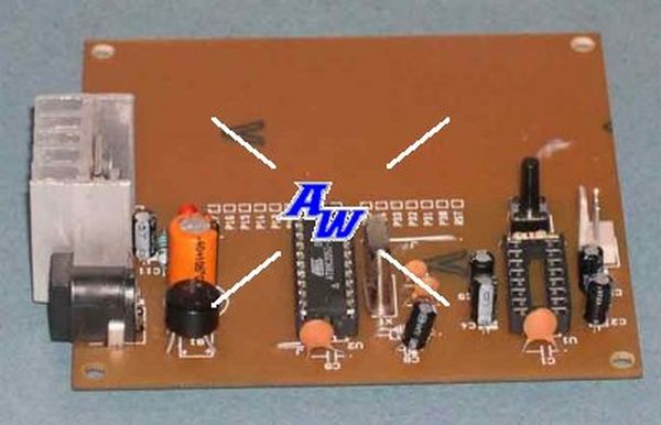
This single sided proto board provides an economical solution for developing and testing the projects around Atmel 20 pin series u-controllers (89Cx051 & AVR)
Figure 1 shows the circuit diagram of proto board. All port connections are available for user interface around the proto area including the power supply pins. MAX232 serial driver is used to provide a 3 wire RS232 interface for connecting to the PC or other rs232 devices. Switch S1 provide a manual reset to u-controller.
The crystal X1, C7 & C8 can be replaced by a three pin ceramic resonator, the pcb has provision for both type of oscillator interface.
For AVR devices the C6 and R2 has to be interchanged, because AVR series have active low reset input also the
Vcc point of reset switch S1 has to be connected to GND instead of Vcc, there is a provision on pcb for the selection of reset type for switch S1.
For printing the pcb files on HP laser printer download the PCBs.zip file and run the Laser.bat file after extracting from the zip file.
Figure 2 & 3 shows the component layout of the proto board pcb and the track patterns respectively.
For more detail: AT89C2051 PROTO BOARD

