Summary of ATMEGA162 LCD OSCILLOSCOPE CIRCUIT
This project describes a digital oscilloscope using the Atmel ATMEGA162 microcontroller and an LCD screen (Hitachi LMG6402PLF), aimed at hobbyists who find commercial oscilloscopes expensive or bulky. The oscilloscope features a maximum sample rate of 40MSPS, input bandwidth of 20MHz, and a 240×128 resolution display. It offers multiple time base settings, digital trigger, and offset adjustments. The design promotes portability and affordability while avoiding the risks and complexities of traditional CRT or PC-based scopes.
Parts used in the LCD Oscilloscope Circuit:
- ATMEGA162 microcontroller
- Hitachi LMG6402PLF LCD screen
- Input circuitry (bandwidth 20MHz, 10K input impedance)
- Power supply (8V to 10V DC, 1A)
- Trigger and offset digital adjustment components
A very nice project cost is a bit high in our country, even hard to find parts Atmel AVR microcontroller series dealing with this type of project is ideal for those who want to… Electronics Projects, ATMEGA162 LCD Oscilloscope Circuit “avr project, microcontroller projects, “
A very nice project cost is a bit high in our country, even hard to find parts Atmel AVR microcontroller series dealing with this type of project is ideal for those who want to learn about
I think part of that is difficult to have the most expensive LCD LMG6402PLF Hitachi LCD Screen LCD Oscilloscope ATMEGA162 microcontroller circuit board have all the details on
ATMEL AVR LCD OSCILLOSCOPE
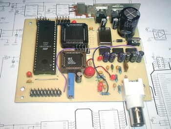
The oscilloscope is one of the the most important tools to be used by any electronics hobbyist but not everybody can afford to have one. As commercial scopes are often too expensive, almost every electronics hobbyist thought at a certain time to build one from scratch. The classical oscilloscope (cathode ray tube) is difficult to build at home because of its size, mechanical fragility, high voltages presence, etc. An alternative solution is the modern “PC oscilloscope”, having the advantage of post-processing and recording capabilities, and kind of reduced complexity. However, this solution is often non-portable, expensive (requires an PC) and dangerous for the PC if not isolated from it’s chassis. The third solution, commonly used these days by all commercial oscilloscope manufacturers, is the digital oscilloscope with LCD screen. Therefore, the authors decided to use this solution, and tried to develop it using common parts from today’s component retailers.
Maximum sample frequency: 40MSPS
Input frequency: 5MHz
Maximum displayed frequency without aliasing: 10MHz
Input circuit bandwidth: 20MHz
Display resolution: 240×128 total, trace resolution 200×125
Sensitivity: 40mV/div
Coupling: DC
Input impedance: 10K
Power supply: single DC source 8V..10V, 1A
No incremental mode
Time base: 1s/div, 500ms/div, 200ms/div, 100ms/div, 50ms/div/, 20ms/div, 10ms/div, 5ms/div, 2ms/div, 1ms/div, 500us/div, 200us/div, 100us/div, 50us/div, 20us/div, 10us/div, 5us/div, 2us/div, 1us/div, 500ns/div
Trigger: digitally adjustable
Trace offset: digitally adjustable
source: LCD OSCILLOSCOPE CIRCUIT LCD Oscilloscope Circuit files alternative link:atmega162-lcd-oscilloscope-circuit.rar alternative link3 alternative link4