Summary of Attiny85 EMF detector
This article outlines a simple guide to building an EMF detector using an Attiny85 microcontroller instead of an Arduino. The project involves creating a circuit on a breadboard, testing it, and then soldering components onto a protoboard for the final build. It includes explanations of electromagnetic fields and lists the necessary materials for assembly.
Parts used in the EMF Detector:
- Protoboard also Breadboard
- 1 Attiny85
- 2 green leds
- 1 yellow led
- 1 red led
- 1 CR2025 Battery
- 1 CR2025 Battery case
- 4 40 Ohm resistors (optional)
This is a simple tutorial to create an EMF detector. You can use Arduino for this job, but is better use a microcontroller called Attiny85. It is possible program it throe the Arduino interface.
What is a Magnetic Field [from Wikipedia]
An electromagnetic field (also EMF or EM field) is a physical field produced by electrically charged objects. It affects the behavior of charged objects in the vicinity of the field. The electromagnetic field extends indefinitely throughout space and describes the electromagnetic interaction. It is one of the four fundamental forces of nature (the others are gravitation, weak interaction and strong interaction).
The field can be viewed as the combination of an electric field and a magnetic field. The electric field is produced by stationary charges, and the magnetic field by moving charges (currents); these two are often described as the sources of the field. The way in which charges and currents interact with the electromagnetic field is described by Maxwell’s equations and the Lorentz force law. From a classical perspective in the history of electromagnetism, the electromagnetic field can be regarded as a smooth, continuous field, propagated in a wavelike manner; whereas from the perspective of quantum field theory, the field is seen as quantized, being composed of individual particles.
The materials of this project are:
- Protoboard also Breadboard
- 1 Attiny85
- 2 green leds
- 1 yellow led
- 1 red led
- 1 CR2025 Battery
- 1 CR2025 Battery case
- (optional) 4 40 Ohm resistors
Step 1: The circuit
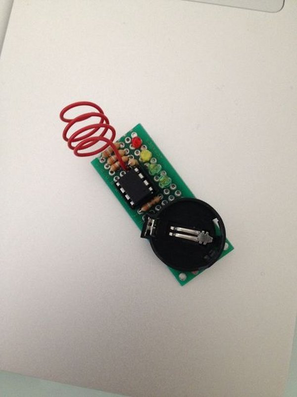
First step is create a circuit on the breadboard. Use a breadboard like in photo and try the circuit before solder it on protoboard. After the test you can use a protoboard to connect the attiny85 to leds and antenna.
For more detail: Attiny85 EMF detector
- What is a better microcontroller to use than Arduino for this project?
An Attiny85 is better to use for this job. - Can you program the Attiny85 through the Arduino interface?
Yes, it is possible to program the Attiny85 through the Arduino interface. - What is the first step in creating the circuit?
The first step is to create a circuit on the breadboard. - How should you test the circuit before final assembly?
You should try the circuit on the breadboard before soldering it on the protoboard. - What is required to connect the attiny85 to leds and antenna after testing?
You need to use a protoboard to connect the attiny85 to leds and antenna. - Does the project include optional components?
Yes, 4 40 Ohm resistors are listed as optional parts. - What defines an electromagnetic field according to the text?
An electromagnetic field is a physical field produced by electrically charged objects. - What are the two sources that often describe the electromagnetic field?
The electric field produced by stationary charges and the magnetic field by moving charges.