1. Introduction
1.1 Problem
Extreme cold temperatures, such as those experienced during the winter in Illinois, pose a significant threat of causing pipes to freeze and subsequently burst. Just this past winter break, our apartment complex sent out an email notifying residents on our floor that several units had unfortunately suffered burst pipes due to the harsh winter weather. This issue isn’t limited to college students like us; it affects many individuals nationwide. It is estimated that over 250,000 homes, on average, experience damage from frozen and burst pipes each year, resulting in annual damage costs estimated to be between $400-500 million. To emphasize the vulnerability of frozen pipes, even a small rupture as tiny as 1/8th of an inch can release up to 250 gallons of water daily.
1.2 Solution
Current approaches to address this issue have proven to be ineffective or have room for improvement. Common methods for preventing frozen pipes include maintaining a minimum temperature of 55 degrees Fahrenheit in the home, running a small amount of cold water from faucets with exposed pipes, and adding insulation or heat cables to the pipelines. However, alternative methods like the use of antifreeze are considered harmful to the environment, wildlife, and human health.
While the first three methods are a good starting point, what happens when a resident forgets to set the temperature or leave the faucets running? Even if these measures are taken, the associated utility costs and energy wastage can be excessive and inefficient. Moreover, situations where a resident is away from home for an extended period and cannot return promptly exacerbate the problem.
Our proposed solution involves the creation of an automated system that notifies the resident through a smartphone alert when a pipe is at risk of freezing and potentially bursting if left unattended. The notification subsystem is triggered by the temperature sensor subsystem. Additionally, a third subsystem will be employed to open a valve, allowing cold water to flow through the pipe. This combination of features provides the resident with the means to take further action, buying them time and automating preventive measures such as keeping water flowing to prevent pipe freezing.
1.3 Visual Aid
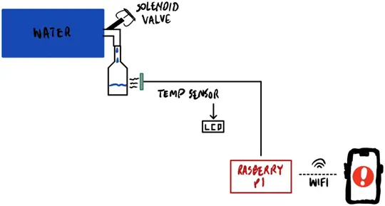
High-Level Requirements
1. The system activates when the temperature sensor output falls within the range of 13.0-14.0 °C.
2. A single push notification is transmitted to the mobile device via Wi-Fi immediately upon detecting a low temperature reading.
3. To prevent the pipe from freezing, 75 mL of water is dispensed into the pipe over a 5-second duration, ensuring a continuous flow to inhibit freezing. Given that the solenoid valve has a ½-inch diameter, this may necessitate the addition of an extra filter at the valve opening to reduce the flow rate.
2. Design
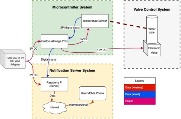
2.1 Block Diagram
2.2 Physical Design
Please be aware that the diagram below does not include dimensions. This omission is due to the fact that the setup has not been physically assembled yet, and the design will be completed in collaboration with the machine shop once all required components are on hand.
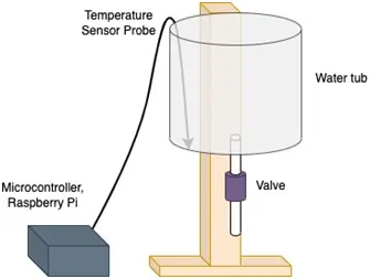
The diagram above illustrates the arrangement of the main physical elements in our project setup. A wooden frame will support the plastic water tub, enabling the attachment of the pipe and valve to the lower exterior. This setup facilitates the natural flow of water from the reservoir to the valve, driven by gravitational water pressure. The temperature sensor probe will be routed over the top of the tub and positioned at the bottom, ensuring the most accurate representation of the water temperature within the pipe.
2.3 Microcontroller Subsystem
The microcontroller subsystem plays a crucial role in connecting the physical and electronic/software aspects of our project. At its core, the microcontroller subsystem revolves around the ATmega328P microcontroller integrated circuit. This component will be programmed to receive input data from the temperature sensor and relay signals to both open the valve and communicate with the Raspberry Pi for sending notifications. The ATmega328P, along with its associated components, will be soldered onto our custom printed circuit board (PCB). This PCB will interface with the Raspberry Pi 4 I/O, the temperature sensor’s digital output, and the LCD screen. To program the microcontroller, we will utilize the USB 3.0 Type A port and the Arduino IDE software [6].
The microcontroller will only be activated by the DS18B20 digital thermometer when it detects an input signal indicating that the temperature has fallen within the specified threshold range of 13-14 degrees Celsius, accounting for an expected tolerance of +/- 0.5 degrees Celsius. This threshold range was thoughtfully selected to ensure that the system triggers itself before the temperature drops below the recommended safe level for pipes, which is 55 °F (12.7778 °C).
2.4 Valve Control Subsystem
To prevent pipes from bursting, it is considered safe to maintain a temperature above 55°F [5]. Based on this threshold temperature, when the ATmega328P microcontroller detects a reading below 55°F from the Waterproof Temperature Sensor (DS18B20), it will activate the 12V DC solenoid valve to allow water to flow into the pipe for a predefined period (approximately -5 seconds). This action will help raise the water temperature inside the pipe, providing the user with additional time to implement a more reliable solution, such as adjusting the thermostat.
Subsystem Requirements:
1. The solenoid valve should have the capability to interface with the ATmega328P microcontroller for the purpose of releasing water into the pipe for approximately 5 seconds.
2. It should be connected to a 12V adapter, which, in turn, is linked to a 5V one-channel relay module or NPN transistor. This intermediary component is essential as the ATmega328P, which operates at 5V, lacks the required power to control the valve independently.
To enable water deposition, the valve will communicate with the PCB and the temperature sensor connected to the microcontroller. Given that the ATmega328P functions at a maximum voltage of 5V while the valve necessitates 12V, an intermediary component is needed to facilitate the electromagnetic passage of the 12V supply when prompted by the temperature sensor. To achieve this, either a relay or an NPN transistor will be employed. Both options function as switches, effectively closing to allow the valve to connect to its power source.
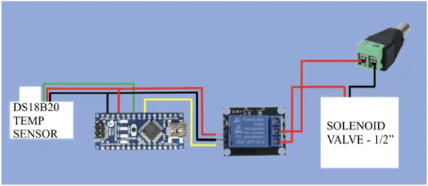
When employing the relay depicted in the image above, we will connect the temperature sensor to one of the digital input pins of the ATmega328P. The relay, responsible for electromagnetically controlling power to the normally closed solenoid valve based on the temperature threshold, will be linked to the microcontroller on one side and to the valve, which is connected to 12VDC, on the other side. [1]
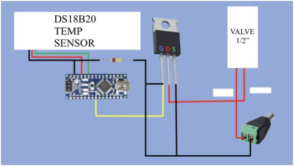
If you opt to use the transistor as shown in the illustration above, the temperature sensor will still be connected to one of the digital pins of the ATmega328P microcontroller. However, in this setup, the drain pin of the 3-pin NPN transistor will be connected to the solenoid valve, while the source pin will be linked to the 12VDC power source.
Currently, we have faced challenges in finding the appropriate relay module that doesn’t come from a third-party source, making the transistor an equally viable alternative. Although using a transistor raises concerns about potential overheating, it eliminates the moving parts found in relays. The repetitive friction of switching the power supply can reduce the lifespan of these moving parts. Furthermore, given the limited use of the transistor in our application, concerns about overheating are not a significant issue.
2.5 Notification Server Subsystem
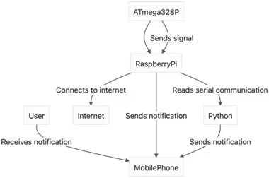
To enhance the user experience and interaction with our system, we will employ software to alert the device user via their mobile phone when the freezing prevention system is activated. The Raspberry Pi 4 Model B single-board computer will be set up as an internet-connected server to transmit these notifications using the internet protocol.
The Raspberry Pi will interface with the ATmega328P through its I/O pins to detect the triggering event and will utilize its built-in 2.4 GHz and 5.0 GHz IEEE 802.11ac wireless capabilities for internet communication. Although the code implementation is pending, we are likely to use Python to capture and process the serial data from the microcontroller on the Raspberry Pi, and a Python push notification API to dispatch notifications to the user’s mobile device over the internet.
2.6 Requirements and Verifications
| Component | Requirements | Verification |
| One-Channel Relay Module | 1. Provide 12 VDC +/- 10% from a
10.8 VDC-13.2 VDC 2. Can operate current within 0-200mA (90mA) |
1. Measure output voltage using an oscilloscope to ensure output voltage is within 10% of 12V.
2. Using a multimeter, connect leads to the coil terminals of the relay and measure. Output resistance should read 50-120Ω( 62.5) (Safe Relay Resistance). |
| DS18B20
Temperature Sensor Probe |
1. System should only be triggered between a temperature of 13.0-14.0 degrees Celsius accounting for the
+/- 0.5 tolerance of the DS18B20 Digital Thermometer |
1. Measure the temperature of the water in the reservoir using an alternate thermometer when the system is triggered to ensure that it is within this threshold range. |
| ATmega328p Microcontroller | 1. Receive temp sensor input and output to display at 3.3 – 5VDC. | 1. Connect LCD and DS18B20 to ATmega. Program chip with code for display and check if data is transferring within the 750ms DS18B20 conversion time. Use an oscilloscope to check operation happens at 3.3 – 5VDC. |
2.7 Tolerance Analysis
Accurately measuring the water reservoir’s temperature plays a pivotal role in the success of our project. The effectiveness of our prevention system relies on the microcontroller receiving temperature data and subsequently alerting the resident through a push notification, while initiating the process of trickling water through the pipe when the temperature falls within the range of 13.0-14.0°C. This temperature range has already factored in the DS18B20 Digital Thermometer’s tolerance of +/- 0.5°C, ensuring that the threshold temperature never drops below the recommended safe pipe temperature of 55°F (12.7778°C). It’s worth noting that the DS18B20 Digital Thermometer is designed to accurately measure temperatures within the range of -55°C to +125°C, maintaining its tolerance within the -10°C to +85°C interval.

The above figure displays the typical performance curve of the thermometer ranging from 0 to 70 °C [8]
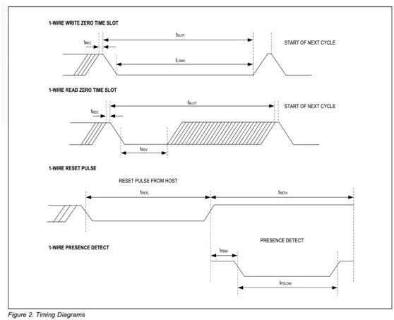
The depicted diagram corresponds to the timing sequences of the thermometer [8].
Based on this quantitative analysis, we conclude that it is indeed feasible to implement the microcontroller and temperature sensor subsystem. When the temperature sensor receives a consistent 5.0V DC voltage within its operational tolerance range, it can provide accurate measurements with minimal error. To maintain stable data transfer, we will incorporate a 4.7kΩ pull-up resistor between the signal and power pins alongside the temperature sensor. A typical gold-banded resistor, with a ± 5% value tolerance, is suitable for our needs. Consequently, the microcontroller will be capable of interfacing with the temperature sensor, transmitting the necessary signals to control the valve, and meeting its operational requirements.
Source: Automated Frozen Pipe Burst Prevention System