Introduction
Our project is an automated pet feeder that is controlled by a wireless infra-red remote control.
As pet lovers, we understand that the responsibilities of life sometimes inhibit pet owners from properly caring for their pets. Pet care should be fun, not burdensome, and so our goal with this project was to assist owners with pet care by providing a system that automates diet management.
High Level Design
Our pet feeder consists of two components. The first component is a remote control that allows pet owners to design the diet plan for their pet. The second component is a feeder that receives instruction from the remote control and refills the pet bowl (to feed the pet) when appropriate. Wireless communication is achieved via IR transmission.
The user interface on the remote consists of a keypad and LCD. The LCD prompts the options the user can select and the keypad allows the user to make a selection and input data. The feeder consists of a motor-controlled food dispenser (where a high torque DC motor is used to turn a wheel in the cereal dispenser) and three weight sensors to monitor the weight of food in the pet bowl. The user interface and the feeder communicate via a pair of IR transceivers and IR endecs (encoder and decoder).
There were two aspects of our project where hardware/software tradeoffs were considered. The first involved the transmission of IR data between the remote and feeder components. Data is transmitted using the IrDA standard, so IR endecs were used to handle the translation from RS-232 to IrDA. Although the signals could be translated in software, handling the translation in hardware allowed us more time to focus on other issues in our project. The second aspect involved low-passing the signals provided by the weight sensors measuring the weight in the pet bowl. Voltage spikes caused by adding to or removing food from the bowl needed to be filtered, and instead of building a low pass filter in hardware, an averaging function was implemented in software. Since surface stability is essential to accurate weight measurements, the reduction in hardware allowed us to construct a more accurate weight sensor circuit.
RS-232 and IrDA (Infrared Data Association) standards were used in this project. RS-232 was used to communicate between the Mega32 chip and the IR endecs. IrDA was used to communicate between the IR transceivers and between the transceivers and the endecs.
There were no patents or copyrights associated with this project.
Program/Hardware Design
Two Mega32s were used to run the two components of this project. The Mega32 on the remote component was responsible for handling the user interface and informing the feeder component when to refill the pet bowl. The Mega32 on the feeder component upon receiving instruction to refill the bowl would activate the motor-controlled food dispenser until the bowl was filled up.
Remote Component
Three functions were programmed into the remote. The user can change the remotes current time, input a new feeding schedule and prompt the feeder to refill the pet bowl.
The setup used to interpret the keypad input is a modified version of the sample code given in Lab 2 tailored for the scavenged keypad we used. Pins corresponding to the rows and columns were separately read in order to determine which key was pressed, and the numeric value of the key pressed was stored in a variable for use in other functions. Figure 2 displays how we wired up the keypad.
Accurate timing is critical to automating the feeder to dispense food according to the inputted feeding schedule. Timer0 was set to a 62.5kHz PWM signal for IR transmission, so to implement an accurate 1ms timing scheme a counting variable that alternated between 62 and 63 (average 62.5) was used. Additional timing variables to count seconds, minutes and hours were directly modified in the timer0 overflow ISR.
Another important design consideration was to have the remote control capable of automating the feeder upon a reset. To accomplish this, the remotes current time and the current feeding schedule are stored in EEPROM and copied back into volatile memory upon reset. However, the timing will not be updated when the remote is turned off. Implementing a device that will track timing even when the remote is turned off is beyond the scope of our current project.
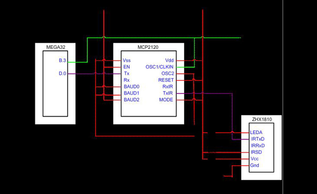
The design for IR communication was based off of a previous 476 project Wireless Electromyograph. A string of ones is transmitted for one minute to indicate that the bowl should be refilled. This signal is outputted as a RS-232 UART through port D.0. A MCP2120 IR encoder converts the RS 232 signal to the IrDA standard. The signal is then transmitted via IR transmission by a transceiver, and is received by another transceiver on the receiving end. A MCP2120 IR decoder then converts the IrDA standard signal back to a RS 232 signal.
To ensure reliable communication, the baud rates of the Mega32 UART and the MCP2120 must match. A 62.5kHz square wave produced by the Mega32s timer0 was used to drive the MCP2120. By hardwiring the BAUD2:BAUD0 pins of the MCP2120 to 100, the clock divider of the MCP2120 is set to 64 and the effective baud rate for the endec was:
![]()
To have the MCU match this baud rate, UBBR was set to:
![]()
More specifically, UBBRL was set to 0xff and UBBRH was set to 0x03.
The IrDA compatible signal was transmitted using a ZHX1810 IrDA transceiver. The device receives 0-5V CMOS compatible signals and contains an IR diode with rise time and optical transmission spectrum that adheres to the IrDA standard. The standard also requires reliable transmission of at least 1 meter, which our circuit meets. The IR transmit
Feeder Component
Three concurrent tasks are run on the feeder component MCU: monitor the weight of the pet bowl, receive instruction from the remote control, and activate motor controlling the dispenser under correct conditions (reception of instruction to feed and an empty pet bowl).
The weight of the pet bowl is measured using two IESP12s, push button force sensors. (A third sensor was included for testing purposes but was not used in the computation of the weight of food). The sensors act as variable resistors that are sensitive to the weight or pressure on top of the push button.
The selection of 1MΩ resistors was to maximize the change in voltage with respect to a change in resistance for the variable force sensor resistor. Figure 6 displays the sensor resistance as a function of weight (gf = force created by a mass of 1 gram). When no weight is present, the sensor resistance will be greater than 100MΩ and the voltage divider will read:
![]()
We anticipated an applied force of 500gf when the bowl is full, which implies the sensor resistance is around 10kΩ and the voltage divider output equal to:
![]()
The following snippet of code was used to calculate the weight of the food bowl.
if (ADCSR.6 == 0)
begin
if ((Aindex%2)==0) ADMUX = 0b11000000;
if ((Aindex%2)==1) ADMUX = 0b11000001;
Ain = ADCL;
Ain += ADCH*256;
sum+=Ain;
Aindex++;
if (Aindex==200)
begin
Aindex=0;
weight = (int)(sum/200);
sum=0;
The output of the three voltage dividers were fed into port A.0, and A.1, which corresponded to the ADC input 0 and 1 respectively. To maximize the accuracy of the A/D conversion, ADCSR was set to 0b11000111 so that the ADC clock frequency was minimized and all 10 bits of the data register utilized. Each ADC channel was sampled sequentially and the weight was calculated to be the average of 200 samples, 100 per channel. The averaging reduces the effect of any voltage spikes caused by weight changes in the food bowl.
When the weight is calculated, the average samples ADC value is compared to an upper and lower weight threshold. The upper threshold of the average sampled ADC value was chosen to be 999 and the lower threshold was chosen to be 850. The use of two thresholds instead of one threshold acted as a Schmidt Trigger implemented in software and reduced unwanted spikes in the determination of whether the weight of food in the bowl was sufficient. Due to the wiring of the force sensor in series with a 1Mohm resistor, the greater the weight of food, the smaller the resistance of the force sensor, and thus the smaller the voltage drop across the force sensor, and the smaller the ADC sampled value at Port A.0 and A,1. The ADC sampled values thus decrease as the weight of food increases. A refill bowl instruction is executed if the average ADC sampled value is above the upper threshold (i.e. insufficient weight of food), and is ignored if the weight is below the lower threshold. In addition, a green LED is lighted if the bowl can be refilled (i.e. insufficient weight of food), and a red LED lighted if the bowl should not be refilled.
The IR receive circuit, as shown in figure 7, is essentially the same as the IR transmit circuit in the feeder component. An important difference, as noted in the Wireless Electromyograph webpage, is that the Tx pin of the MCP2120 must be tied high when receiving IR signals, whereas the Rx pin can be left floating when the device is transmitting IR signals. This is to inhibit the transmit function when receiving signals since the MCP2120 gives priority to transmission and a floating Tx pin may accidentally induce a transmit instruction, when it is supposed to be receiving signals.
A refill bowl instruction is executed when five 0xff bytes are read in succession. At this point, a PWM signal is fed into PORTC.0 of figure 8 below. Through testing, the current frequency and duty cycle setting of the PWM signal was found to minimize the chances of jamming in the food dispenser. The motor is turned off when the weight of the bowl crosses the lower threshold, signified by the red LED turning on. The optoisolator isolating circuit for the DC motor shown in figure 8 was adapted from Lab 5.
Mechanical Design
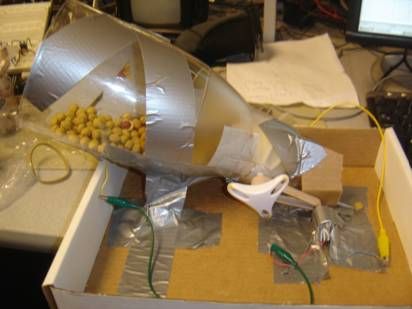
Food Dispenser
A cereal dispenser was used to contain the pet food. The wheel in the cereal dispenser was connected to a high torque DC motor via a thick rubber band so that when the motor was turned on, the wheel was turned and the food would be dispensed. Initially, we had a lot of difficulty getting the wheel to turn as there was too much friction and the pet food was too heavy. The torque provided by the DC motor was insufficient in turning the wheel. Friction was minimized by cutting down the flaps of the wheel which reduced the contact between the wheel and the sides of the cereal dispenser. The cereal dispenser was also tilted at an angle to reduce the weight of the pet food on the wheel. The motor and cereal dispenser was then taped down into position using duct tape and a box to hold the cereal dispenser in position. With this setup we were able to dispense food with minimal jamming.
Force Sensor
The system to measure the weight of the pet food comprised of two force sensors that were placed under the food bowl. The sensors were soldered onto tiny solder boards that were then held together using duct tape. Readings were taken from both force sensors and averaged, as the weight of the food bowl was distributed across the two force sensors.
Results of Design
The final result of our project design accomplished the main goal of designing an automated pet feeder. The remote component was able to acquire and implement a feeding schedule and the feeder component was able to refill the pet bowl at appropriate times and to the appropriate amount.
Speed of Execution
Since feeding times were accurate to the minute, speed of execution was not an issue since the process of refilling the pet bowl at a specified time could be completed within a minute. More specifically, the IR transmission of the refill bowl instruction and the subsequent refilling of the pet bowl took less than minute. In addition, the weight of the bowl was updated at a much greater frequency than one reading per minute.
Accuracy
The final design was able to meet the accuracy requirements as set in our project expectations. By updating timing variables in the ISR, timing was accurate to the minute. Combined with our method of coding a refill bowl instruction as a string of ones sent over a minute, this setup ensured that the pet bowl was refilled at the correct time. In addition, our design of the force sensor circuit and calibration of the MCUs ADC allowed us to efficiently determine whether the pet bowl was full and ensure that the dispenser did not add food when the weight of food was already sufficient.
Usability
The usability of our project as an actual pet feeder is inhibited by the limitations of our mechanical design. Realistically, the feeding component of our device would be susceptible to a rowdy pet who tried tampering with it. However, with the current set-up using duct tape and cardboard boxes, the structure of the pet feeder is not ideal and could be made more stable with better materials.
However, from a user point of view our project is simple to use. The user interface on the remote is instinctive and easy to navigate. Storing schedule and timing information into EEPROM also makes the design very robust. All that is lacking is a timing device that is active even when the remote is turned off.
Safety and Interference
Safety was not a concern in our project since all components excluding the MCU and motor ran on 5V. Also, there were no heavy objects in our design or direct connections to the human or pet body. Interference was also not an issue since our IR signals were transmitted over a very small distance. Also, not many other groups were using IR.
Conclusion
Our project succeeded in meeting the goals that defined our automated pet feeder. By entering a food schedule and time of day into the remote, the device was able to automate the feeding of the pet by instructing the feeding component to refill the pet bowl at the scheduled times. The feeding component also ensured that the contents of the bowl did not overflow, especially if the bowl was already full during a scheduled feeding time.
While our main goal was accomplished, there are features that could be added to this project. Originally we wanted the feeder component to be able to operate independently of the remote. This required that when a feeding schedule or time of day was inputted into the remote, this data would be transmitted to the feeder component via infra red transmission. In addition we hoped to let the user determine the amount per feeding for each feeding time. Both features could not be included because our IR transmission was not accurate enough. We contacted Arthur Gariety, one of the creators of the Wireless Electromyograph project and have come to the conclusion that the source of the noise experienced in our transmission most likely derives from the clock circuit used to drive the IR endecs. That group was able to scavenge a clock oscillator circuit of a much higher frequency and thus was able to use a much higher baud rate for data transmission.
Also, given more time (and perhaps better expertise), we hope to design a better dispensing system that is less prone to jamming and physically more sturdy. The use of a more powerful motor or solenoid could accomplish the former, though acquisition of such a device would send us way over budget.
The design conformed to RS-232 and IrDA standards. All reused code and design was implemented with permission. There were no legal or intellectual property considerations to worry about.
Parts List:
| Item | Number Used | Cost |
| Mega32 chip | 2 |
$16.00 |
| Custom PC board | 2 |
$10.00 |
| Batteries | 3 |
$6.00 |
| Small solder board | 1 |
$1.00 |
| Freescale solder boards | 7 |
Scavenged |
| ZHX1810 IR Transceiver | 2 |
$8.10 |
| MCP2120 IR Endec | 2 |
Sampled |
| IESP12 Force Sensor | 3 |
Sampled |
| LCD | 1 |
$8.00 |
| DC Motor | 1 |
Scavenged |
| Keypad | 1 |
Scavenged |
|
Total |
$49.10 |
For more detail: Automatic pet feeder Using Atmel Mega32