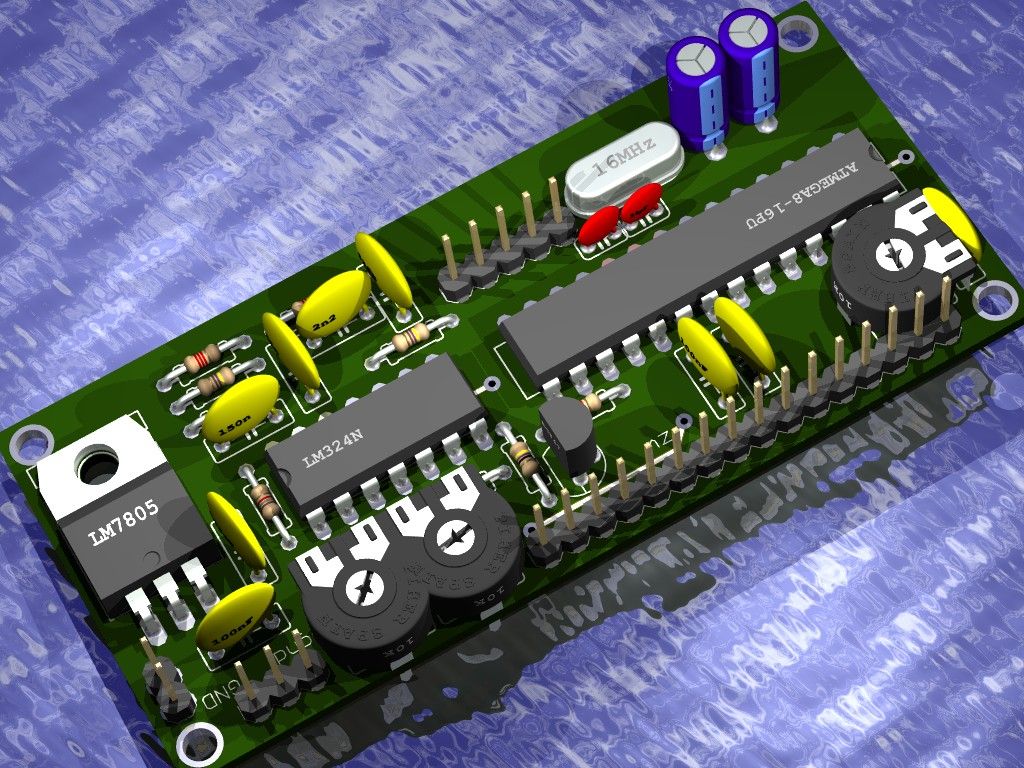
AVR acoustic spectrum analyzer, based on Atmega8 AVR microcontroller, operational amplifier, and few other components. Use any HD44780 compatible LCD or VFD, connect audio signal, and enjoy the effect 🙂 You can build in this into your amplifier, pc, car-audio, or other device. On this moment device support following displays: 16*2, 20*2, 24*2, and 20*4. If you have one which this device not support, please contact me and i will try to adapt code for it. There are two pcb’s which exactly fits behind the display, one for the 8*2 connector displays, and one for 16*1. You can attach a small keyboard to change display brightness (vfd also supported), change sensivity, choice the display effect. Settings are saved to the eeprom memory.
Project site: diy.elektroda.eu/analizator-widma-akustycznego-v2/
And here is how it works on 20*2 VFD
“czulosc” and “janosc” are in polish, they means “sensivity” and “brightness” 🙂 And they can be changed 🙂
Step: 1 Make board
Use the eagle project files or PDF’s to make a PCB, choose 16*1 or 8*2 connector depending on your display. There is also top layer with components values. See schematic for part list. You can connect a small keyboard to 5pin connector, there is no pcb for keyboard, just use 5 buttons and connect all to the ground.
Step: 2 Program the AVR
First of all you need to program your AVR with code from the attachment, if you are using 16*2 display you need to flash the 16*2 version code, etc. Use any avr proggramer. You will need to setup fusebits as shown, for example on burn-o-mat, the avrdude GUI. You need to set the external crystal 16MHz, and activate the CKOPT fusebit. That’s it.
Step: 3 Connect audio signal
There are 3 ways to connect audio signal:
a) Signal ground to “Agnd” on board, in this case analayzer ground and audio ground can not be connected together.
b) Analyzer can be powered symmetric, +-2.5V, “Agnd” will become power ground and audio ground.
c) If analyzer and our output device grounds must be connected together, and there is no way to power analyzer with symmetric supply, you must somehow raise signal to 2.5V height. You can do this by connect the grounds together, raise the signal up with R/R resistor divider (about 100Kohms) connecting them between gnd and supply, signal through 1uF capacitor to resistor divider and then to IN pin.
Step: 4 Fast calibration
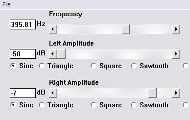
You will need a “function generator” program, i use “FG Lite” (on download page). Connect and power-up analyzer, sound connect to line-out of your pc card, ground to Agnd. Attention – grounds can not be connected together! Function generator set to sine, frequency about 400Hz, gain at about 80%.
Left potentiometer set so that was leaning out just one bar (eventually two, depends on frequency), highest as possible. If gain be too large, you will see other leaning out bars – this is bad. Now, change generator frequency to 10KHz, and right potentiometer set in the exactly same way. Done.
For more detail: AVR acoustic spectrum analyzer using Atmega8 microcontroller


