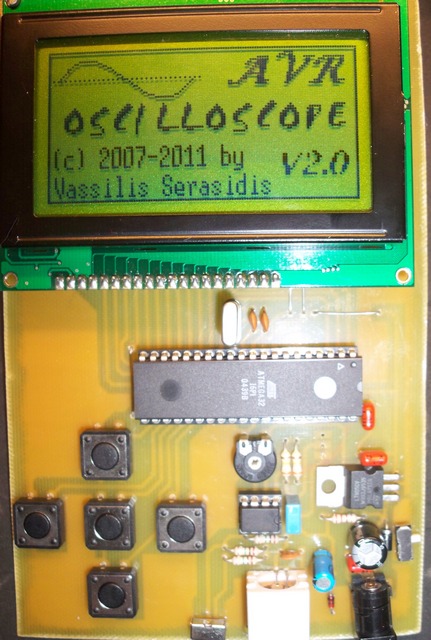
Summary of AVR LCD Microcontrolled Oscilloscope using ATmega32 microcontroller
This article describes a microcontroller-based oscilloscope project using an ATmega32 microcontroller with a KS0108 graphical LCD. It measures signal frequencies from 10Hz to 7.7kHz and displays signals with a 128x64 pixel screen. Powered by 12V DC, the circuit generates +8.2V and +5V for the ICs and can measure voltages from ±2.5V or 0 to +5V depending on input mode. The project firmware is written in C using WinAVR and AVR Studio 4, with a custom graphics library for display rendering.
Parts used in the AVR LCD Microcontrolled Oscilloscope:
- ATmega32 microcontroller
- KS0108 graphical LCD (128x64 pixels)
- Power supply (12V DC input)
- Voltage regulator circuit producing +8.2V and +5V
- Input selector switch (S1, for AC/DC)
- Input division switch (S2)
- Probe with 1:10 voltage division
Features | ||
|
Introduction
A few months ago as I was surfing on the net, I saw an oscilloscope based on PIC18F2550 microcontroller and a KS0108 controller based graphical LCD. That was Steven Cholewiak’s web site. I had never seen before so amazing microcontroller-only oscilloscope. That was realy impressive circuit, so I decided to design something like that but in C language instead of assembly that I was using all those years.
The best solution for me was the WinAVR as it bases on open source AVR-GNU compiler and it works perfect with AVR studio 4. The graphics library that I used, was made by me specific for this project. It’s not for general use. If you want to include it to your source codes, you have to convert it according to your needs. The maximum input signal speed who can show up this oscilloscope is 7.7 kHz in square signal. For other signals (sine or triangle) the frequency is lower ( almost 1 kHz) for having clear view of the signal.
Description
The operating voltage of the circuit is 12V DC. By this voltage, the power supply is producing 2 voltages. +8.2V for IC1 and +5V for IC2 and IC3. This circuit can measure from +2.5V to -2.5V or from 0 to +5V dependent by S1 position (AC or DC input). By using probe with 1:10 division you can measure almost 10 times higher voltages. Moreover, with S2 you can make an extra division by 2 the input voltage.
For more detail: AVR LCD Microcontrolled Oscilloscope using ATmega32 microcontroller

