So, you’re going to a conference/meetup/nerdfest and you want to do something that sets you apart from normal people. An LCD namebadge powered by an ATtiny2313 is a great way to do that. This is a general purpose LCD display unit powered by a 9V battery and a simple voltage regulator circuit (the same 7805 circuit you see absolutely everywhere). It’s no-frills, but it can be etched, drilled and soldered in 1-3 hours by an experienced hobbyist, and 3-6 by a beginner/intermediate one. It all depends on how many issues you encounter along the way, and how well-equipped you are to fix them.
I found this great instructable that shows how to breadboard this same circuit, and this is based on it.
This is my first project that I’ve taken from breadboard to schematic to protoboard to functioning PCB, so I’m going to try and document some of the pain I went through along the way, as well as some things that helped, in hopes that your first end-to-end electronics design is a little easier.
Step 1: Supplies
Tools
- Decently-sized Breadboard (I used an 840-hole)
- Breadboard hookup wires (I prefer stiff hookups for on-board work and longer flexible ones for ISP hookup and long runs)
- Multimeter with conductivity testing mode (beep!) and DC voltage mode
- Soldering iron – I have a 50-watt that I love.
- An etching vessel – see PCB etching instructables.
- A drill and PCB drill bits (I used sizes 65 and 75). A mini drill press helps too.
- A hot glue gun (optional, but barely – the wire broke twice on me with very little force applied)
- An AVR ISP programmer (I built a USBTinyISP)
- Helping hands (optional)
Components
- An ATtiny2313 (or 2313A, which is what I used – functionally equivalent)
- An HD44780 LCD with a single row of pins
- A 20-pin DIP socket
- A 7805 Voltage Regulator (you can definitely get away with a low-amperage one too, I just had these laying around)
- A 100uF capacitor
- A 10uF capacitor
- A 330-ohm resistor
- A 10K-ohm resistor
- A 1N4004 diode (other diodes will probably work fine too – make sure to read the datasheet though)
- A 5K linear potentiometer (or between a 1.5K and 2.5K resistor if you don’t care about contrast adjustment – YMMV)
- A 9V wired connector – preferably one that doesn’t suck (I have suck ones.)
- Breakable male header strip – you’ll need 16 pins, but these usually come as 40-pin strips.
Materials
- Etchant – again, see etching instructables
- Solder, preferably very thin stuff. I’m using .015 diameter.
- PCB, single sided, whatever color you see fit.
- Hot glue sticks –
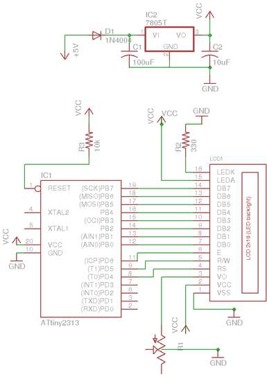
Step 2: The schematic
I’ve attached the eagle schematic. Feel free to let me know your opinions about it in the comments – I’m very new to eagle, so I know it could be better. Study it enough to know what’s up.
Step 3: Breadboard It
You are welcome to jump ahead right to making the PCB and diving in, but I recommend breadboarding it beforehand so you know what you’re getting into. I’ve attached a picture of what my breadboarding ended up looking like. See this instructable for intimate breadboarding details.
Step 4: Programming
Once you have it all hooked up, use git to grab the source code. Here’s the LCD library I wrote that you’ll need to compile against:
git clone git://github.com/hank/lcdiesel.git
You can view the source code for this project here:
https://github.com/hank/life/tree/master/code/avr/lcd/display_chars
I’ve made some tarballs for your convenience, but getting the latest version of the code is preferable. There’s no good way to do this from github at the moment – it’s in my huge repository of junk that I don’t recommend you clone (it’s big..).
All this code is written in C, a real programming language. Sorry, Arduino folks. I encourage you to learn AVR programming if you want to complete this project – it’s completely worth it. The Arduino is great for getting excited about microcontroller development boards, but there’s nothing better than ordering a chip from Digikey for a dollar and being able to do just as much with it as with a $40 Arduino. </rant>
You’re going to need avr-gcc, avr-objcopy, and avrdude. I’ll leave that up to you to figure out. Make sure to set your fuses up without CLOCKDIV8 and at 8Mhz. I used my favorite fuse calculator to generate the following settings line:
avrdude -c usbtiny -p t2313 -U lfuse:w:0xe4:m -U hfuse:w:0xdf:m -U efuse:w:0xff:m
If you’re going to get into AVR programming, learn about the fuse calculator – take it for a spin!
For more details, click: AVR LCD Namebadge Using ATtiny2313


