Sometimes we need our microcontroller to interact with more human readable information. It will be better for us if we could make it display the words not just blinking the LED. Today most modern gadget such as mobile phone and PDA, use LCD (Liquid Crystal Display) for interacting with us. In this project we will learn how to use the 2×16 LCD for displaying the room’s temperature.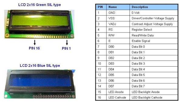
Actually driving the LCD hardware directly is a complex task, but luckily we don’t have to do that; in the market they have already put it together in one package the LCD display hardware and the microcontroller that control it, so our task will be easier now as we only talk to the build in microcontroller inside. The most famous on the market is the 2×16 LCD with LED backlight using Hitachi HD44780U or the equivalent microcontroller, this 80 pins microcontroller is a special dot matrix LCD driver controller with low power consumption and able to use 4-bit data or 8-bit data interface; my suggestion is to have this HD44780U datasheet near you as we walk through this project.
In this project we will use the AVRJazz Mega168 board from ermicro with has build in precision centigrade temperature sensor LM35DZ connected to the PORTC (ADC1), the diagram bellow will show you how to connect the 2×16 LCD to the board:
The simple 2×16 LCD with 16 pins connection is shown on the first schema, usually the VO pin for controlling the LCD contrast is connected to the trimpot that works as voltage divider, but because the board and LCD is using the same supply 4.5 volt and the voltage needed is very small (less then 0.25 volt) for readable/normal contrast you could connect it directly to the ground.
The enhance version of this 2×16 LCD connection schema is shown on the right; on this schema we use the PWM signal to power the LCD backlight LED through the TIP 120 Darlington pair transistor but you could change this with other type of transistor that capable of handling more than 100mA needed by the LCD backlight LED such as BC639 or it’s equivalent.
We will use the PWM to switch the LCD backlight LED on and off; because it use a lot of power (about 100mA), so instead of turn the LED just on and off, we just make it gradually bright when we turn on and gradually dark when we turn off. Ok let’s take a look at the C code that makes this work:
For more detail: AVR LCD Thermometer Using ADC and PWM Project
About The Author
Ibrar Ayyub
I am an experienced technical writer holding a Master's degree in computer science from BZU Multan, Pakistan University. With a background spanning various industries, particularly in home automation and engineering, I have honed my skills in crafting clear and concise content. Proficient in leveraging infographics and diagrams, I strive to simplify complex concepts for readers. My strength lies in thorough research and presenting information in a structured and logical format.
Follow Us:LinkedinTwitter