A simple, low component count phase locked loop that locks onto and detects the amplitude of an incoming baseband 7 bit Barker code using a switched resistor demodulator that is driven directly by a microcontroller’s output pins.
- Balanced modulators using resistors and a microcontroller’s output pins.
- Locking into oncoming Pseudo-noise (PN) stream.
- Microcontroller modulates its own crystal oscillator frequenc inside a Phase-Locked Loop (PLL).
- Extending the output range of a bipolar op-amp to opearte near ground.
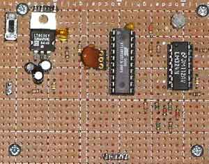
Photo 1. The only semiconductors in the circuit are the microcontroller
and a quad opamp. This picture was taken before the offset adjustment
for the signal level measurement circuit was installed. Some surface
mount components are on the other side of the board.
Click on the image above for a larger version.
Downloads
Download the AVR Studio assembly source for the ATtiny12 7 bit Barker beacon: Brkshf061015B.asm
The AVR Studio assembly source for the ATtiny2313 demodulator / 7 bit Barker source: bark3p061015A.asm
Download the AVR Studio assembly source for the ATtiny2313 181.818 kHz Barker code transmitter: rf7bark061015B.asm
Find updates at www.projects.cappels.org
Related web pages:
Digital Lock-in Milliohmmeter http://cappels.org/dproj/dlmom/dlmom.html
Experimental 1 kHz Synchronous Demodulator http://cappels.org/dproj/syncdet/syncdet.html
This simple circuit includes three synchronous demodulators and two
integrators that process the demodulation signal. The modulation is achieved by switching
the microncroller’s I/O pins between high impedance and current sinking states, so no additional
analog switches or multipliers are needed. The first op-amp stage (pins 8,9, and 10) is used
to provide a uniformly low output impedance to the demodulators. It can be converted to a gain
stage or a filter, provided there is sufficient loop gain to maintain a sufficiently low output impedance.
Introduction
The circuit in figure 1 is that of a synchronous demodulator that meets these requirements, and additionally, it operates from a single positive power supply. The circuit will be described in detail later in this page. The ATtiny2313 microcontroller is used as a voltage controlled crystal oscillator and Barker code generator, and could be replaced with small scale logic devices. The code generation is initiated by interrupts from the microcontroller’s internal 8 bit timer, and there is plenty of time available for control and computational tasks that could used to modulate the Barker code stream with data or to decode an incoming stream.
This implementation, using a 7 bit Barker code with a 148 microsecond chip rate, was intended as a means of proving a concept. The low chip rate was selected because it is easy to deal with using the inexpensive equipment available to me. A longer Barker code and a faster chip rate would increase performance, and merely scaling the design will provide those improvements.
stream of the 7 bit Barker code. The Barker code gates a 50 milliamp
constant current source made of the two 2N4401 transistors.
As with the ATtiny2313, this function could be easily replaced with discrete logic. In addition to the code output, the ATtiny12 also has a sync output that occurs one time with each repetition of the Barker code.In an experiment to visually illustrate operation of the demodulator, I connected a photo diode between the signal input and “ground” on the demodulator circuit in Figure 1 and used the 7 bit Barker code beacon shown in Figure 2. There was no electrical connection between the beacon and the demodulator, except that their power supplies were plugged into the same electrical outlet. During some experiments, the beacon was battery operated, and I did not notice any difference in performance between those experiments in which the beacon was battery operated and those experiments in which the beacon was powered from a power supply.
Before testing, the free run frequency of the demodulator had to be set. Channel one of a Tektronix TDS-2002 oscilloscope was connected to the punctual Barker code output pin on the ATtiny2313 (ATtiny2313 pin 18), and scoope was sync’d to the sync output of the ATtiny2313 (ATtiny2313 pin 16). Channel two of the scope was connected to the Barker output of the ATtiny12 on the beacon assembly (ATtiny12 pin 7) and the infrared LED on the beacon was covered so demodulator would not detect the beacon’s signal. While simultaneously viewing the prompt Barker code generated on the demodulator and the Barker code generated by the beacon, the free run frequency of the demodulator was adjusted so that rate of local prompt Barker code generation was fraction of a word per second slower than that of the beacon.
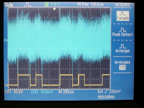
Channel two of a Tektronix TDS-2002 oscilloscope was then moved to the output of the voltage follower stage in the demodulator (LM324 pin 8) and the IR LED on the beacon was uncovered. letting some of the light from the LED fall on the photo diode connected to the demodulator. Photo 1 and Photo 2 show what the signals looked like.
Photo 2. This is a screen shot while the scope (Tektronix TDS-2002)is in the sampling mode. The blue trace shows the incoming signal from a photo diode, with the noise provided by fluorescent lights and a dangling 1 meter clip lead. The yellow trace is the prompt Barker code generated by the ATtiny2313 on the demodulator. The scope was synchronized to the sync output on the ATtiny2313.
Signals
Experimental 1 kHz Synchronous Demodulator, examines the sensitivity of the demodulator and its ability to measure very small signals in spite of the circuit relying on a quad op-amp that is not known for its low noise performance or exceptional DC stability.
The main problem with using a simple square wave for low level measurements is that they are susceptible to noise, especially at the signal frequency and its odd harmonics. One solution to this susceptibility is to transmit and demodulate with a signal that is made of many different frequencies, one that effectively looks like random noise, but isn’t really random. This signal is referred to as pseudo noise, or PN, in many signal processing articles. Figure 3 and Figure 4 show the 7 bit pseudo random sequence used in this series of experiments. This 7 bit sequence is the 7 bit Barker code. All versions of a particular Barker codes that are inverted and/or shifted in time are the same Barker code.


