Work is of two kinds: first, altering the position of matter at or near the earth’s surface relatively to other such matter; second, telling other people to do so. The first kind is unpleasant and ill paid; the second is pleasant and highly paid.
Bertrand Russell
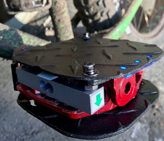
The joy of measuring work or in this case power that comes from biking. Units that parse the tiniest efforts in specialized crank arms and bottom brackets are pretty expensive. There was recently even a new variety that somehow used algorithms related to your rear tire pressure to measure…something: http://www.velonews.com/2017/09/bikes-and-tech/aro… Now that Load Cells and their attendant amplifiers have become very cheap and the software is really easy to use I have adapted a couple of these for use in a modified bike pedal. When you are done with your ride the WEMOS D1 inside the pedal publishes its data to a couple charts on https://thingspeak.com using MQTT. A wireless Qi charger for the unit makes it easy to maintain.
Step 1: Gather Your Materials
1.The heart of the unit is the micro load cells–I used the ones from:
They come with included amp and are really cheap–about $6.
A pair of them worked well connected in parallel–and even though the weight limit seemed iffy it worked for all my rides. If you want to go for the 50kg limit you will find it below:
http://www.robotshop.com/en/micro-load-cell-50-kg….
2. WEMOS D1 mini–https://www.banggood.com/D1-Mini-NodeMcu-Lua-WIFI-ESP8266-Development-Board-p-1044858.html
3. Boost lipo-to 5 volts: PowerBoost 500 Basic – 5V USB Boost @ 500mA from 1.8V+ Adafruit
4. Charging board for lipo:TP4056 1A Lithium Battery Charging Board Charger Module DIY Mini USB Port
5. Old Mt Bike pedals that you are about to discard anyway
6. Lipo battery 500-1000 mAh
7. Neopixels–cut off three from some old project.
8. Hall sensor: KY-003 Hall Magnetic Sensor Module–this should be a digital output type with LED
9. On/off button: Adafruit Rugged Metal On/Off Switch – 22mm 6V RGB On/Off
10. Qi charger: https://www.amazon.com/Wireless-Charge-Receiver-U…
Give or take the total cost for these parts is about $30.
Step 2: Build the Mechanicals
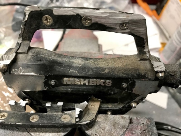
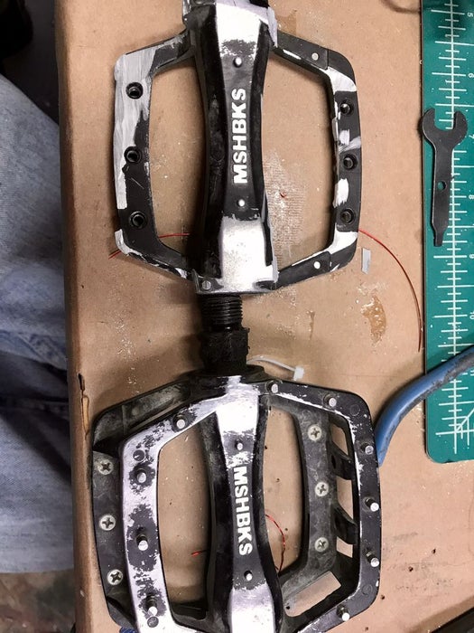
The load cells are really easy to use. Sparkfun has a great introduction to load cells and the HX711 amplifier that you need to make them work: https://learn.sparkfun.com/tutorials/getting-star… The setup and the software that you need to download and calibrate them are all on their website. Load cells have to be cantilevered out with a stable platform on one end and the load you are measuring on the other. In the design I used a metal cutting wheel to get rid of the upper deck on the pedal. It is aluminum and easily done. Each pedal is slightly different but you want to develop a stable platform to mount the load cells with bolts. They are tapped for 5mm on the stable end and 4 mm on the load end. You will have to drill mounting holes in the lower deck to accommodate these holes. The upper deck is made out of aluminum diamond plate from the big box store. I placed a crosspiece of heavier aluminum bar to share the load over the ends of the load cells and mounted the diamond plate over this.
Step 3: Sensors and Such….
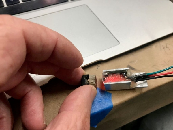
The hall sensor is enclosed in epoxy within an aluminum housing for stability. The sensor included an LED within it that made testing it much easier. The Neopixels were epoxied to the upper deck cover under holes drilled to the size of the round LED turrets. The Qi charger was epoxied to the lower deck cover on the outside. It has to be in close proximity to the charger unit and cannot be mounted under the aluminum shell. The unit itself seems to resist the torture that occasionally results from stepping on this side of the pedal. The output of the Qi charger is a microUSB connector that is led in to the charger unit (TP4056) through an opening that is sealed with epoxy.
Step 4: Electronics
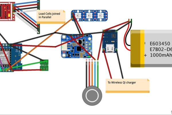
The fritzing diagram will show you the layout of all the electronic components. Get started by wiring up the load cells in parallel. Four wires come out of the strain gauges that are inside the aluminum bars. They are color coded and you connect like colors together and then attach them to the HX711 amplifier as described in the Sparkfun tutorial. The software will then lead you through getting a calibration factor for your load cells and then using the example program to test and make sure that your setup is weighing things correctly. I temporarily attached a oled output so I could carefully monitor the setup–and even tried it on my bike. Unfortunately you can’t read the output well in the light which resulted in using the LEDs for color calibrated output instead. The components are mounted on a perf board and the on/off switch is connected between the charger and the booster. The battery and the charger unit and booster are located on one side of the pedal and the WEMOS and amp are located in the other.
Step 5: Software
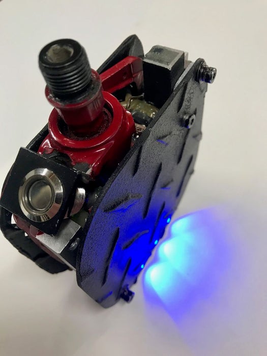
The software uses one function to obtain the maximum weight applied to the pedal within a 5 second measurement window and then another function to figure the cadence for the next 5 second window. I looked through a variety of sources for figuring the power associated with each stroke and you can get pretty “granular” with this material. The weight on the pedal will be vary with each stroke from some maximum to a minimum with the other pedal stroke. It will have a myriad of inaccuracies associated with this including measuring force in the down direction only. So compromising I designed the software to look for the highest kg weight for a set period and figured it would compensate for a variety of errors. If you want you can have the system sample constantly, find the average wt and then double it for both pedals. The cadence is measured in a separate timed function so the two samples with not interfere with each other. The calculation for power is force, distance moved and cadence. P[W] = F[N] * l[mm] * w[rpm] * 2 * pi / 60,000
The software has a running average for both weight and power that stops when the bike stops. About once a minute it dumps the averages into two arrays with a capacity for 100 integers each to record your history. The light output from the 3 LEDs varies with power output and runs from a cool blue to a hot red if you get into Lance territory. At the end of your ride you set the pedal so that the Hall sensor is constantly on and after about 30 seconds it will begin the upload sequence for the thingspeak web page. So make sure your back at home within wifi range when you do that or you can set up your phone for a wifi hub if you are on the road. You have to change the code for the name of your network and your wifi password. The information for uploading MQTT on the thingspeak is located here and I just followed their example carefully: https://www.mathworks.com/help/thingspeak/use-ard…
You will have to set up a channel and set up the graphs that you want to populate. You get your api key as well as the channel number to allow you to upload to the correct spot. The minimum time between uploads is 20 seconds so it will take about 1/2 hour to upload an 90 minute ride. You can also add cadence to the upload or anything else that you want recorded. The Qi charger straps on to the the pedal to recharge while you’re downloading. The software goes into wifi sleep when its done.
Step 6: Using It
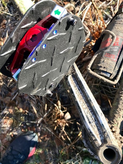
I have been using the pedal power meter on my fat tire bike–you can see in the photo its the only thing not covered in mud. (Notice the bear spray in the water bottle cage–Alaska biking has its own unique risks…) To activate the hall sensor just use a standard magnet that comes with a bike computer and stick it onto the crank arm where it will activate the sensor with each pedal rotation. I used a web based calculator that estimates your power output on a hill climb given your weight, height of your climb and time and found the result was within spitting distance of what the meter was reading. http://www.u.arizona.edu/~sandiway/bike/climb.htm…
Source: Bike Power Pedal IoT
