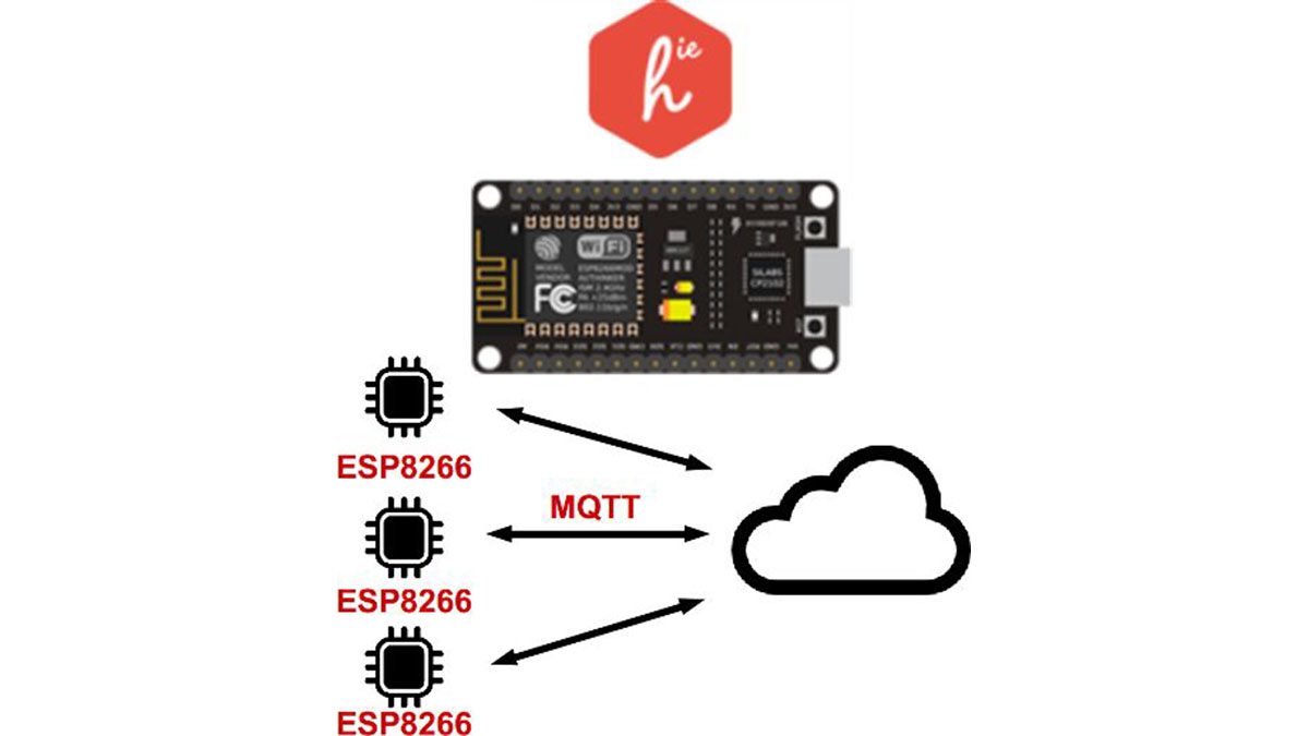
This instructable is part of my DIY Home Automation series, check out main article “Planning a DIY Home Automation System“. If you don’t know yet what Homie is, have a look at homie-esp8266 + homie from Marvin Roger.
There are many many sensors. I’m covering the very basic ones in order to give reader the requirements to get started building “something”. That might not be rocket science but that should actually work.
If you don’t have the parts, watch out for my upcoming instructable “Sourcing Electronic Parts From Asia“.
Let me add a few buzz words : IoT, ESP8266, Homie, DHT22, DS18B20, home automation.
Topic should be pretty clear now 🙂
Also, this instructable is now also available from my personal page : http://stuffblog.dullier.eu/
Step 1: Getting Started
Conventions
This instructable uses D1 Mini clones. These are WiFi enabled Arduino compatible controllers using ESP8266 chip. They ship in very small form factor (~34*25mm) and are dirt cheap (~3-4$ for clones).
I’ll illustrate each build using a D1 Mini, a breadboard and some sensor(s). I include a Bill Of Materials (BOM) for each but will skip obvious things like jumper wires and breadboard (mini or full). I’ll focus on “active parts”.
For wires/cables in diagrams (Fritzing + AdaFruitFritzing library), I used:
- Red/Orange for power, usually 3.3V. Sometimes it will be 5V, be careful.
- Black for ground.
- Yellow for digital data signals : Bits are traveling and can be read as-is by chips.
- Blue/Purple for analog data signals : No bits here, just plain voltage that must be measured and computed to understand what’s going on.
Homie for ESP8266 ships a dozen examples, that’s where I started to build this instructable.
Breadboard
The D1 is quite breadboard friendly but will save only one row of pins up and down.
Each example will have the D1 on the right side and the components on the left side. The upper and lower power rails will be used to carry either 3.3V or 5V.
Note
Homie examples are built as “.ino” sketches for Arduino IDE. My own code is however built as “.ccp” for PlatformIO.
This will make very little difference as sketches are simple enough to be copy/pasted whatever your tool of choice is.
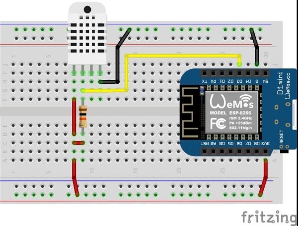
Step 2: Temperature & Humidity : DHT22 / DHT11
Building the device
The DHT22 uses :
- One digital pin to communicate with the controller, connect it to D3
- Two wires for power (3.3V or 5V + GND)
- The digital pin must be kept high (connected to power), for this we use a resistor between power rail and data pin
Code
The PlatformIO project can be downloaded from : https://github.com/amayii0/Homie-DHT22
The original Homie example is here (but does not use a sensor) : https://github.com/marvinroger/homie-esp8266/blob/…
For DHT22, use DHT sensor library (ID=19)
BOM
- Controller : Wemos D1 Mini
- Resistor : 10KΩ
- Sensor : (one of these)
- DHT22 : I’ve used the 4 pins kind which requires an extra resistor. There are 3 pins modules shipping as SMD which includes the resistor.
- DHT11 : This is cheaper but less accurate, check your requirements
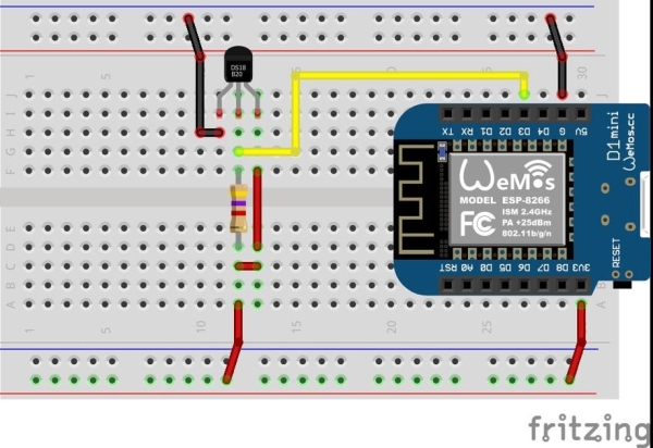
Step 3: Waterproof Temperature : DS18B20
Building the device
The DS18B20 uses :
- One digital pin to communicate with the controller, connect it to D3
- Two wires for power (3.3V or 5V + GND)
- The digital pin must be kept high (connected to power), for this we use a resistor between power rail and data pin
The DS18B20 is a 1-wire sensor. It uses a bus and as such multiple sensors can use a single data pin.
It is also possible to NOT use 3.3V/5V to power the sensor, this is called parasitic power mode. See datasheet for details.
Code
The PlatformIO project can be downloaded from : https://github.com/amayii0/Homie-DS18B20
Like for DHT22, the original Homie example is here (but does not use a sensor) : https://github.com/marvinroger/homie-esp8266/blob…
For 1-Wire bus, use package OneWire (ID=1)
For DS18B20, use DallasTemperature (ID=54)
BOM
- Controller : Wemos D1 Mini
- Resistor : 4.7KΩ
- Sensor : DS18B20, pictured is a waterproof one
- 3 pins screw terminal to ease connection of cable to the breadboard
Step 4: Light : Photoresistor / Photocell (digital : On/off)
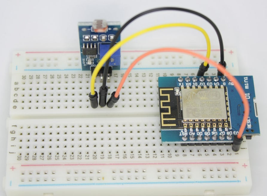
Building the device
(Sorry, don’t have a Fritzing component for the digital photocell)
The photocell digital module uses :
- One digital pin to communicate with the controller, connect it to D3
- Two wires for power (3.3V + GND)
Its possible to use an analog photocell but this is not documented here, see Adafruit excellent article “Using a Photocell“.
Note: In this example there’s a potentiometer on the sensor board. It is used to set the limit between “light” and “dark” ambient light. When reading 1 light is off, therefor reading 0 means light if on.
Code
The PlatformIO project can be downloaded from : https://github.com/amayii0/Homie-Photocell
BOM
Controller : Wemos D1 Mini
Sensor : Photosensitive / Light Detection Module
Step 5: Light : Photoresistor / Photocell (analog)
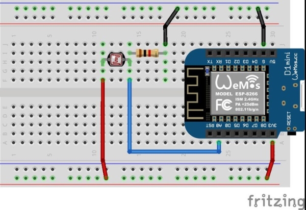
Building the device
The photocell analog sensor acts as a resistor. It will connect between an analog input and 3.3V.
A resistor is put between GND and data pin to create a voltage divider. The purpose is to create a known range of values:
- If there is no light, photocell will basically block VCC, thus connecting GND to your data pin : Pin will read nearly 0.
- It there is a lot of bright light, photocell will let VCC flow to the data pin : Pin will read nearly full voltage and as such near to max (1023).
Note : Analog pins values are read in a 0-1023 range using analogRead. This is not practical to deal with 1 byte values, for this the Arduino map function will help reduce from 0-1023 to (for instance) 0-255.
For calibration of min/max values for your sensor, use a sketch like this one from Arduino.
Code
The PlatformIO project can be downloaded from : https://github.com/amayii0/Homie-PhotocellAnalog
BOM
- Controller : Wemos D1 Mini
- Sensor : Light Dependent Resistor (LDR) / Photoresistor
- Resistor : 1K or 10K, need to calibrate based on your cell
References
- PiDome server source code for lighting condition of a location
- Adafruit’s “Using a Photocell“
- “Photoresistors” here at instructables
- Some damn crazy “Photocell Tutorial” if you want some math and graphs
Step 6: Optical Detector : QRD1114
Building the device
Code
BOM
References
- Physical Computing : QRD1114 includes sample code to read sensor and use interrupt for rotary encoder + precise PCB design
- QRD1114 Optical Detector Hookup Guide at Sparkfun
Step 7: Final Words

This instructable is a very short one to explain basic monitoring.
To go further we’ll need to connect relays, IR emitter… This will hopefully be covered later on as free time allows me to. The major difference is that we won’t just “read” (is there light?) but also “write” (turn light on!).
Source: Building Homie Devices for IoT or Home Automation