Introduction
The objective of this project was to build a keyboard based on capacitive sensors and then use the MCU to create MIDI encodings for all notes played. The output from the sensors is detected by the MCU using its ADC capability. The sound is played directly by the MCU via a piezo speaker using Pulse-width modulation (PWM). The MCU communicates via serial protocol with an executable interface that has the capability to record MIDI format songs, play them using an integrated Windows Media Player control, and modify them using a hex editor interface.
High level design
The design consists of an MCU, a front end Visual Basic interface, an LCD display, capacitive sensing based keyboard, a piezo speaker, and an LED display panel. A block diagram schematic is displayed below. This idea grew out of an idea to make a full-scale computer keyboard using capacitive sensors. It was deemed that it would be nice to have a way of recording one’s own music compositions and playing in a convenient, portable MIDI file.
The project is a musical instrument with capacitive sensor input. When a person’s finger is brought close to the electrode attached to the capacitive sensor, a voltage is produced by the capacitive sensor to indicate a button press. The input interface of this musical instrument is electrodes with different area sizes. These different areas produce different capacitive sensor reading and can be detected by the ADC in MEGA32 to decide on the keys pressed. The keyboard consists of 8 keys corresponding to 8 notes on 1 octave. There is an additional button on the top left side of the keyboard which allows user to switch to a different octave.
The notes played will then be converted into midi format and sent to the PC through serial communication. At the PC, a visual basic program is used to receive midi data and save these data in a midi file. The midi file can be played using any software capable of playing the standard midi format file.
As an add-on to the instrument, there is an LCD screen which shows the current and previous notes pressed. It also displays useful information about calibration status, ADC reading, etc. To make our project more interesting, there is a visualization add-on built from LEDs. When a note is pressed, corresponding LEDs light up and decay slowly.
Hardware Design
Setup
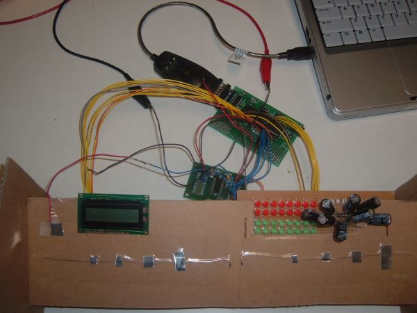
The photo below shows how the entire system fits together.
The last design shown gave the best performance of all the layouts considered. This can be attributed to the fact that the discreteness avoids any ambiguities and sets clear thresholds for each note.
Capacitive sensors
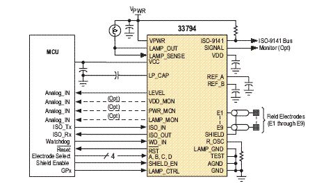
The capacitive sensor chip used is MC33794 . These were donated to the lab by Freescale, and thus their availability and (zero) cost gave them a definite edge over other similar products on the market, most of which had very long lead times and high minimum order quantities. These sensors have 9 channels and give an analog voltage output between the range of 0-2 V, indicating the voltage potential with respect to ground of the sensor connected to the sensing chip. In this project, as per discussion with Prof. Land and tests on several potential materials, a thin aluminum sheet was chosen due to its high sensing ability and malleability.
Speaker
The speaker used to generate sounds is the piezo speaker used in the Lab 1 (stop clock). This speaker is used to generate all the desired frequency sounds by the MCU directly using PWM as described in the software design section.
LED display
The LED display is comprised of 8 strings of 4 LEDs each, of which each string has 2 red and 2 green LEDs. A capacitor is placed across the red LEDs to cause a lighting delay, giving a smooth rise effect whenever the string is activated. The red LEDs and green LEDs are placed parallel as shown below such that the entire string can be driven directly by the MCU port pins (+5V). Below is the circuit diagram for one of such LED strings:
The LED display is also activated in idle mode where the MCU sweeps through all the strings creating a sort of “screensaver” effect.
Software Design
Capacitive sensing algorithm using ADC
The E-field sensing chip, MC33794 has an internal mux to select one of its 9 input channels. The controls for this mux are, in this case, driven by MCU port pins to control which channel is read. The analog output from the chip is converted to an 8-bit digital value by the ADC on the Mega 32. This value is then used by the calibration algorithm to detect the touching of one of the keys.
Calibration Strategy
Efficient and reliable calibration was one of the main challenges of this project. Several keypad designs were tested for reliability, and the designs were scales up and down to look for any changes in performance. However, it was found that a persistent problem was the variation in the sensor reading from user to user and also for the same user over a period of time. In order to mitigate this issue, a startup calibration scheme was designed. This scheme sends the used messages via the LCD display to press all the keys sequentially so that the system is calibrated properly for each sitting. As a result, the variation in readings is mostly dealt with, including the hitherto encountered problems with different users applying different pressures to the keys.
Sound generation
In order to generate sound, pulse width modulation was used to generate notes of different frequencies. Timer1 compare interrupt was used here to calculate time accurately for the purpose of generating square pulses with desired frequency. Referring to the skeleton codes from previous projects, we set prescaler = 256 so that each cycle is 16us. We can then easily modify the period of interrupt by varying OCR0. The values for OCR0 for different notes are given below:
flash char notes[] = {0,240,212,188,180,160,142,126,120,106,94,90,80,71,63,60};
| OCR0 value | Note | Actual Frequency |
| 0 | none | none |
| 240 | C(0) | 130.81 |
| 212 | D(0) | 146.83 |
| 188 | E(0) | 164.81 |
| 180 | F(0) | 174.61 |
| 160 | G(0) | 196.00 |
| 142 | A(0) | 220.00 |
| 126 | B(0) | 246.94 |
| 120 | C(1) | 261.63 |
| 106 | D(1) | 293.66 |
| 94 | E(1) | 329.63 |
| 90 | F(1) | 349.23 |
| 80 | G(1) | 392.00 |
| 71 | A(1) | 440.00 |
| 63 | B(1) | 493.88 |
| 60 | C(2) | 523.25 |
Formula for calculating the OCR0 values are given below:
Each tick = 16us.
Period = 16us * OCR0 * 2
Frequency = 1/Period = 1/16us/OCR0/2
The output of the waveform is through PORTB.3. The output of PORTB.3 will be toggled each time timer0 compare interrupt is reached. To play a note, we can simply set OCR0 to the appropriate value according to the notes[] table.
LCD display
The LCD display is used for communicating with the user during the startup calibration process and to display important information about any keys pressed. The LCD displays the last four notes played and the frequency of the last note played during regular operation, and displays the key to be pressed by the user during calibration.
As the user presses a note, the MCU detects it and determines the corresponding hexadecimal MIDI code. This information is then sent via the serial port to the computer to enable recording. In order to allow this, the MIDI code was researched to determine the values associated with a MIDI sound such as the start byte, note byte, stop byte.
Serial Communication Protocol
The MCU sends information via the RS-232 serial port. Information is sent using a UDRE interrupt that sends information as soon as a byte is ready to be sent.
Visual Basic Interface
The Visual Basic front-end was designed in order to provide a convenient interface for a MIDI device such as the keyboard designed in this project. When recording is enabled, the program records all data sent to it by the MCU using the serial interface and keeps a running count of the recording size. After the user opts to stop recording, the program prompts the user for a filename and then appropriately stores the recording. In order to successfully create a MIDI file, it prepends a header file with the proper file-length count as required by MIDI specifications. The header file characters are hard-coded into the program and the characters pertaining to filesize are added to it during the save procedure. The play button plays the file using a control that activates Windows media player. Using the Open file button, MIDI files are displayed in hexadecimal format and can be edited by the user. This was a major challenge as the file had to be opened and closed in binary format and the chars typecasted properly such that extraneous style characters are eliminated while storing the file and converted appropriately to be compatible with the Visual Basic textbox display format. The screenshot below shows the program in operation.
This project has a user-enforced speed of operation, starting with calibration to playing music. The timer interrupts are used to keep track of duration between notes as per MIDI specifications.
The sound generated by the piezo does not sound too much like a piano, although the sound is of the correct frequency. This is because the PWM is essentialy a square-wave generator. In order to smooth the sound, an opamp based integrator was tested. However, this turned out to be ineffective due to the RC constants obtained and the internal capacitance of the speaker and was thus not implemented in the final design. However, by setting the timbre of the MIDI file properly in the header file, a nice piano-like sound was successfully obtained. There continues to be some variance in the E-field sensor readings, but that is inevitable in such a design and we are pleased to have been able to reduce the problem so an extent that it does not hinder normal operation.
There are few safety issues with this implementation. Care was taken such that there is no shorting/bad connection and that the user does not touch any metal parts directly.
This project’s development or usage does not cause any sort of interference to other projects. The sound generated is possibly the only signal created by the project.
The design is highly usable by one and all, especially due to the calibration technique that ensures customized operation for each user. The keyboard can be operated in two modes: one where the tune is played directly at the hardware level and the other where it is connected to the computer to make a recording. The executable can be used on any computer that has the proper control files (provided in the zipped folder).
No. Name 1 Atmel Mega32 2 Prototyping board for Mega32 3 Solder board 4 MC33794 sensor 5 MAX 233CPP for serial communication 6 Serial connector 7 LEDs 8 Capacitors 9 Resistors 10 Power supply 11 LCD 12 Aluminum sheet 13 Piezo speaker For more detail: Capacitance sensor MIDI keyboard Using Atmel mega32