Introduction:
One Sentence Sound Byte:
“Grillzilla – A wireless meat grilling thermometer which alerts the user whether their entrée is cooked according to USDA recommendations via LCD and voice feedback.”
Summary of what we did:

As the weather starts to get warmer a common type of social gathering that occurs is the barbeque. Barbeques are all about the variety of drinks, good weather, interesting company and the grill. Meats of all types are cooked to each person’s preference on the grill, and it is of the utmost importance that the host fulfills his guest’s requests. Unfortunately, the person who is hosting the party is often obligated to stay near the grill and oversee the progress of his work. This can seriously hamper the griller’s social interaction and also makes him smell like raw beef until long after the party.
As a solution we built a device that allows the griller to detach him or herself from the grill and mingle with the people that he or she is trying so hard to impress with his stellar cooking skills. Such interaction could include a sporting game of volleyball, or a game of badminton. Either way such activities are not possible when one is tied up in cooking for the entire barbeque.
We came across this concept because of experience with a similar device that Brookstone sells – the “Grill Alert Talking Remote Thermometer” (here). However, we did not merely copy Brookstone’s design. Instead, we recreated the functionality of the Grill Alert system, and improved upon several of its features that users have complained in reviews (see amazon.com and cnet.com). In addition, we designed our device with cost in mind, as Brookstone’s Grill Alert is quite expensive for the average consumer ($75.00 US).
Our transmitter and receiver for the device was built on the foundation of Meghan Desai’s work in Fall ’05 (“Wireless Protocol”) and Spring ’04 (“Wireless Telemetry”) with the Radiotronix RCT-433 and RCR-433 RF chips . This was the first system that we built, and it took us about a week to get it fully functional. To get an idea of how to wire all the components we put it on a breadboard first. We then tested for proper communication with a modified Meghan Desai’s code (Figure 1).
After debugging the transmitter and receiver circuits, we transferred over the design to two of Bruce Land’s custom PCB boards for the ATMega32. This required a fair amount of soldering and debugging.
After both boards and the LCD were able to function without the aid of the STK500, we moved on to building our digital thermometer of a cheap thermistor probe (here). In order to accomplish this task, we had to research the dynamic range of our thermistor, as well as the application of a Wheatstone bridge to get a linear voltage response from its measurements (here). We also performed some empirical experiments on our thermistor probe to ensure that it was calibrated properly.
We attempted to incorporate a large LCD display, the Hyundai HGS2504, into our design for the receiver. Although supposedly easy to write for, we were not successful in displaying anything on the device (see Figure 2). This was after we studied numerouscodeexamples and consulted multiplesources for help. After struggling with the LCD for four days, we decided that we had to move on if we wanted to complete the project. Luckily, we sampled a 4×20 LCD display from Bruce Land, and quickly incorporated it into our design. This design mishap turned out to be fortuitous in several ways, as we will discuss later.
Next, Jeff split off to work on implementing buttons for our receiver device, as well as an audio amplifier for an 8 ohm speaker. Much breadboarding, soldering, and flights of fancy ensued (Figure 3). Matt concurrently worked on the software design of the receiver. This included several user menus, incorporation of USDA recommended cooking temperatures into LCD feedback, and a speech alert system.
High Level Design:
Rationale and Sources for project idea:
We came across the idea for a digital thermometer because Matt had had some experience with a product that Brookstone, a specialty tools and electronics store, manufactures and sells. The product is called the “Grill Alert TM Talking Remote Thermometer” and is listed on their site for $75. We thought that it is an interesting idea to have a wireless thermometer so that one doesn’t have to stay standing at the grill while their meat cooks. In addition, we thought it would be a challenge to recreate Brookstone’s product with commonly available and cheap parts – the ATMega32 microcontroller, Radiotronix RF chips, a generic thermistor probe, a 4×20 line LCD, and a LM386 audio amplifier.
Background Math:
The only component that involved extensive math of our own in this project was the temperature probe. Other components such as the DPCM used for speech, error control coding for RF transmission, and fixed point techniques for various calculations in our software design are covered in their respective sections of the ECE 476 website.
The most significant calculations were for empirically finding a relationship between the temperature probe resistances as a function of temperature. Since this relationship is highly nonlinear, we had to choose a range of temperatures that would fit within a relatively linear range. According to an article found in Sensors magazine, “ You can obtain a more-or-less linear output voltage from a Wheatstone bridge/thermistor combination over a 40°–50°C range.” From studying the USDA recommended cooking temperatures that of our selected types of meat, we chose this range to be 106 to 210 °F. The general schematic for this Wheatstone bridge is pictured in Figure 5. As per the article’s recommendation, the bridge resistance (R in Figure 5) was chosen to be the thermistor’s resistance in the middle of the cooking range. This value was found to be approximately 2.2kΩ.
Next, we performed an experiment in the kitchen of Phillips hall to derive a relationship between the thermistor’s resistance, the voltage of the Wheatstone bridge, and temperature. In addition, this experiment verified our design choices mentioned previously. This experiment required holding both a commercial temperature probe and the thermistor in a pot of water that we slowly heated on a stove (Figures 6 and 7). We took measurements of the resistance (R T in Figure 5) across the thermistor and voltage (V out in Figure 5) of the Wheatstone bridge for every five degree change in water temperature. Our exact experimental circuit is pictured in Figure 8. VBIAS was set as 5 volts in anticipation of this circuit’s use on our transmitter protoboard. Using Excel we then plotted the findings of our experiment, and extracted regression lines from the data. Figure 9 shows the voltage of the Wheatstone bridge vs. temperature of the boiling water, while Figure 10 demonstrates the resistance of the thermistor vs. temperature. Note in Figure 10 the relatively linear range of resistance from 110 to 210 degrees. In addition, the equation for the linear regression of Figure 9 was ultimately used in our software design. Note that in Figure 9 that the voltage of the circuit was not measured for lower temperatures. To further improve the accuracy of our device, we could have plotted the voltage for these temperatures and made the equation in our microcontroller piecewise.
Math was also used to calculate the percentage the level of doneness of the meat. We played around with several equations implemented with fixed point math in our software. In the first equation, the doneness percentage is calculated to be :

However, this equation increased the percentage too slowly at low cooking temperatures and too wildly as current temperature approached the desired temperature. Thus, we ended up using the simpler equation:
![]()
Although this equation starts the percentage high (around 40% depending on the type of meat being cooked), we believe it provides a more accurate representation of “doneness” to the user.
To implement speech we used the AT&T text to speech demo to acquire the actual speech. We then downsampled and compressed the speech using the instructions and programs on Bruce Land’s speech compression page. All math and coded techniques are discussed on site as well.
Logical Structure:
The logical structure of our design consisted of two main components – the transmitter base station with temperature probe and the receiver with LCD and speech feedback. The base station takes in voltage measurements from the Wheatstone bridge circuit described above. These voltage measurements are converted into a temperature value through the ATMega32’s analog to digital converter. This temperature is then inserted into the payload of a data packet. These data packets are fully described in Meghan Desai and Yiling Li’s Wireless Telemetry project from ECE 476 in Spring ’05. These packets were then transmitted every second with the Radiotronix RCT-433 chip using Meghan Desai’s transmission driver. A logical overview of this system is pictured in Figure 11
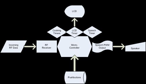
The receiver’s logical structure is far more complex than the transmitter. This is largely because the receiver must both parse the incoming RF data into a temperature measurement while simultaneously outputting text information to a LCD and speech via Differential Pulse Code Modulation (DPCM). A single timer interrupt in the ATMega32 microcontroller directs the output of information to either an LCD or pulse width modulator. In addition, a press of any of the four pushbuttons attached to the unit changes the information displayed or speech output at any time. The logical structure of the receiver is displayed in Figure 12. The timing and hardware used to achieve these outputs are further described in the sections entitled “Hardware Design” and “Software Design” below.
Hardware/Software Tradeoffs:
Most of the components of our griller system had clearly defined roles in either in software or hardware so we did not really need to decide where to implement them. The wireless receive and transmit functionality was implemented in both hardware and software, but since we were using Meghan and Yiling’s driver we did not really have to worry about any compromises. The only part that needed some thought was the temperature probe. Because the probe’s resistance varies non-linearly with temperature, we could have chosen to interpret the resistance into a temperature completely in the Mega32. However, we feel that the cost in time and effort would not have been worthwhile, especially with such readily available information about Wheatstone bridge applications. The Wheatstone bridge makes the change in voltage across the thermistor linear as a function of temperature. This allows for the interpretation of the temperature much easier. Using hardware to simplify the software complexity helped out greatly in this instance, but over all we did not really have the need to strike a balance between the two.
Another large hardware tradeoff we had to make was the choice to use the smaller 4×20 LCD display as compared to the large 256 x 128 graphical display that we ordered from AllElectronics. Although we originally embraced the challenge of writing to this large LCD, we realized after about a week that we would not finish the project in time if we did not move on in the design of our project. However, this choice did not come without positives. For example, the power supply of the graphical display required a regulated -24 volt power source. This would have added on significantly to the area of our protoboard design, and could have ultimately made our receiver too large to be portable. In addition, the graphical display required a significant amount of time in order to write pixels over its entire area. This might have been impossible to accomplish in real time alongside speech and RF reception, whereas the 4×20 LCD was much more manageable to use in practice.
In addition, we would have liked to implement the full set of digits from 0 to 200 in the speech feedback of the Grillzilla for time and temperature. This would have required the following words and phonemes:
| One | Eleven |
| Two | Twelve |
| Three | Thir |
| Four | Fiff |
| Five | Teen |
| Six | Twen |
| Seven | Hundred |
| Eight | And |
| Nine | |
| Ten |
However, the inclusion of these words and phonemes would have not left us room for phrases such as “Your meat is almost done!” in the flash memory. In addition, we calculated that we would not be able to fetch information from EEPROM in time enough for the ATMega32 to modulate the PWM signal to create recognizable speech. Thus, we ultimately decided that the Grillzilla would utter full phrases rather than the complete set of numbers. Perhaps another algorithm for implementing speech in the ATMega32 other than DPCM would have been useful, but this was not within the scope of our original design goals.
Finally, one trade off that we made in the software for the transmitter was for the equation used to convert the voltage measurement from the Wheatstone bridge into a temperature value. Matt first designed a fast algorithm without any floating point variables involved. The granularity of the temperature value resulting from this algorithm was too large, however – on the order of 5-7 degrees. Thus, Matt designed another algorithm.
Relationship of our design to industry standards:
Because we transmit information wirelessly on the 433 Mhz band, we have to follow the Section 15 FCC standards of transmission for low-power non-licensed transmitters. Accordingly, we refer to the document “Understanding the FCC Regulations of Low-Power Non-Licensed Transmitters” as well as parts of the full Section 15 protocol. Because our device is unlicensed it does not interfere with devices that run on different bands. In addition, it is able to take interference from other RF transmissions without great malfunction – i.e. if a packet is not received, the Grillzilla does not accidentally tell you that your meat is ready for consumption. In addition, we followed the USDA guidelines for the proper cooking of various meats, as well as suggested guidelines from professional cooking sources at the Cornell Hotel School. Figure 13 below shows the suggested temperatures from the USDA that we used.
Intellectual Property Considerations
Surprisingly, there are very little patent considerations in the Grillzilla. The Radiotronix RCR-433 and RCT-433 components are patent pending, so if we wanted to manufacture our device commercially we would eventually have to license the use of these chips. We are sure that the ATMega32 has patents on it as well, but we could not any through research. The LM386 doesn’t have any patents associated with it as well. Most importantly, Brookstone’s Grill Alert product doesn’t have any patents associated with it. Finally, we acknowledge Meghan Desai, Yiling Lee, and Bruce Land for all of the intellectual property in their code that we incorporated into our project.
Program (Software) Details
The design of the software for the Grillzilla transmitter is relatively simple compared to the receiver. The A/D converter for the device is set to use AVCC on the ATMega32 as its voltage reference, and the result is set to be left adjusted. Thus, the equation for the A/D converter result in ADCH and ADCL is.
![]()
This result is then used in our equation to determine the temperature, which is:
temperature = fix2int(float2fix(-2.16577695*ADCH + 560));
The fix2int and float2fix functions are from Bruce Land’s fixed point math page, which the specific coefficients in the equation result from inverting the regression equation derived from the data in Figure 9.
Every second ADCH is retrieved and run through the equation for the temperature, and the value that results is fed into the payload of a data packet. This information is padded with the appropriate packet data using the generate_data() function, and then transmitted. Another A/D reading is then requested, and the microcontroller waits another second for the process to repeat. Note that a packet count is sent in the payload of the packet as well. This information is used in the receiver to determine if data packets have been lost, which ultimately determines whether the temperature data is valid and should be incorporated into the user feedback.
The software for the receiver is more complicated due to the wide array of inputs and outputs of the program. The simplest input to the receiver program is pushbuttons. These are connected to Port A and debounced every 125 ms by the program’s state machine. The state machine’s four conditions determine whether the button has been pressed or not, and resemble the state machines we used in all of the in-class labs this semester (see Figure 14).
In addition to the state machine for the pushbuttons, there is one that determines which menu of the Grillzilla is displayed. Figure 15 shows this state machine in full detail. When the unit is first turned on, a welcome screen is displayed. After a short delay, the main menu of the screen is displayed (Figure 16). In this menu, pushbuttons 1 and 2 change which of the three menu lines of the screen is selected. This selection is indicated by an arrow in front of the selected line on the left hand side of the screen (see Figure 16). When pushbutton 3 is pressed, the selected meat, preparation, or timing mode is cycled. This selection is reflected in the selectedMeat, selectedPrep, and timerMode variables, and determines what information is displayed on the next screen.
When pushbutton 4 is pressed in the main menu, one of two things happen. If self timer mode is set to yes, the receiver proceeds to display the timer menu. However, if timer mode is not selected the grilling screen is displayed. Figure 17 shows the timer menu screen. In this menu, pushbuttons 1 and 2 move the blinking cursor on each digit of the time left and right. This display corresponds to the variable of the time that will be modified when pushbutton 3 is pressed. After the user has selected how long they would like to grill, a single press of pushbutton 4 displays the grilling menu screen.
The grilling menu screen comes in two flavors depending on whether the timer mode is selected or not. In either case, once the receiver unit enters this state the RF receiver is enabled and the incoming temperature data is immediately recorded. Figure 18 shows the version of the grilling screen that is displayed when timer mode is disabled. On this screen the desired temperature is displayed according to which meat and preparation the user selected in the main menu. In addition, the current temperature is displayed according to the incoming RF data. When a dropped packet is detected by the software, the current temperature displays the phrase “NoRange”. In addition to the current and desired temperatures, the percent that the meat is done is displayed. This piece of the program was especially tricky to write, as fixed point math had to be smartly exploited so that the display of the LCD and reception of RF data was not adversely effected.
If the timer mode is selected, a version of the grilling screen depicted in Figure 19 is shown. The time in this screen is count down until it reaches 0: 00:00, in which case the phrase “Expired” appears under the phrase “Time:”. Note that in both Figures 18 and 19 that the packet number is displayed as debugging information in the top right corner of the screen.
Note that in the main and timer menus, the LCD is refreshed only if a button is pressed. This occurs through the use of four LCD buffers and the functions menuPrint() and timerPrint(). These functions modify the LCD buffer strings depending on a multitude of variables that are effected by the user’s button presses. At the end of the execution of each of these functions, LCDPrint() is called. This function takes the LCD buffer strings, clears each line of the LCD screen, and sends each string to the correct line.
Throughout program execution, there is the possibility of voice feedback. For example, when the unit is turned on it exclaims “Grillzilla”! In addition, when the current temperature almost reaches the desired temperature, the device says “Your meat is almost done”. Also, when the current temperature reaches the desired temperature the device says “Your meat is done!”. Finally, when button 3 is pressed on the grilling menu screen the device says “Your meat is not done”.
This speech was implemented through DPCM via the PWM output of the ATMega32 as mentioned earlier in this report as well as used extensively lab 2 of the class. The speech was especially hard to incorporate into the design of the receiver’s software, as it must take priority over the state machines and LCD display to function properly. Thus, the time base for the state machines and cooking timer as well as the speech output functionality was implemented in a single ISR (Timer 0 Overflow). In addition, Boolean flags were used extensively to lock out the processing of RF data, triggering of the state machine, counting down the cooking timer, and calling any LCD print function while speech was initialized or in progress. Overall, the design of the code for the Grillzilla receiver is not particularly complex with respect to data structures or algorithms used. However, the integration of the various input and output sources as well as careful detail to the menu displays provided a significant programming challenge. There wasn’t any attempted part of the software that didn’t eventually work without all of the using debugging and careful layout. See the appendix for our commented code.
Referenced Code:
Bruce Lands’s fixed point math routines: macros and optimized multiply
Bruce Land’s DPCM coding techniques: MATLAB programs here and here, and test program here
Meghan Desai’s RF transmission and reception programs: rx.c, tx.c, and txrx.c
Codevision’s LCD driver.
Parts List:
| Component | Qty | Price | Total |
| Atmel Mega32 | 2 | $8.00 | $16.00 |
| Custom PCBoard for Mega32 | 2 | $5.00 | $10.00 |
| Solderboard for Audio Amplifier | 1 | Salvaged | $0.00* |
| Radiotronix RCT-433-AS RF Transmitter | 1 | $3.50 | $0.00* |
| Radiotronix RCT-433-RP RF Receiver | 1 | $4.50 | $0.00* |
| Thermistor Probe | 1 | $4.00 | $4.00 |
| Graphical LCD (Hundai #HG25604) | 1 | $18.50 | $18.50 |
| Character LCD (4×20) | 1 | Sampled | $0.00* |
| 8 Ohm 0.2W Speaker (26SP08WR) | 1 | $1.25 | $0.00* |
| 9V Battery | 3 | $2.00 | $0.00* |
| 4-button Pushbutton Pack | 1 | Salvaged | $0.00* |
| Budget Total: | $48.50 |
For more detail: The Grillzilla Using ATMega32