
This article describes a method to decode four pushbuttons using only two I/O pins on I/O-constrained microcontrollers like the ATtiny12, AT90S2323, and AT90S1200A. The circuit uses bidirectional sensing across two pins with resistors to detect three states: open, pulled high, or pulled low. By driving one pin while monitoring the other, the system identifies which of the four buttons is pressed.
Parts used in the 4-Button AVR Circuit:
- ATtiny12 microcontroller
- AT90S2323 microcontroller
- AT90S1200A microcontroller
- 39k resistor
- Two pairs of pushbuttons (total 4 buttons)
- 10k resistors for button connections
- VCC power supply
- Ground connection
- PORTB bit 3 I/O pin
- PORTB bit 4 I/O pin
Just the solution for AVR applications in which I/O is tight, such as the ATtiny12. This should work well on other kids of controllers that have independently controlled I/O direction registers, such as PIC and 6805 controllers.
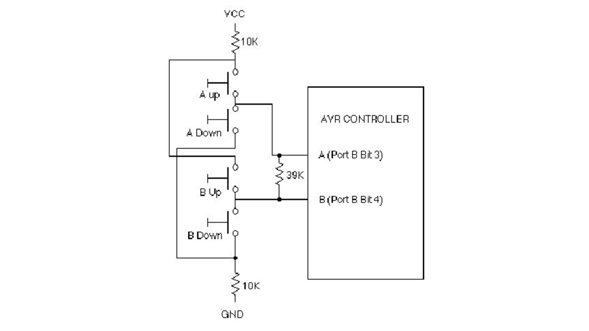
This is a solution was devised for those I/O limited 8 pin controllers like the AT90S2323 (though I tested it on an AT90S1200A).
In principle, the circuit senses three states of the pushbuttons: Open (no button down), Pulled Up, and Pulled Down. The process is this: Pin A (PORTB bit 4)driven high through a resistor and the other end of the resistor is looked, at Pin B (PORTB bit 4) to see if it is being pulled high, low, or not being driven up a button at all. Then Pin B is driven and the other end of the resistor (Pin A) is looked at.
In the circuit, a 39k resistor is placed across the two I/O pins to allow each pin to drive the other through the resistor. The two pair of buttons connected identically, except that one pair of buttons is connected to pin A (PORTB bit 3) and the other pair of buttons is connected Pin B (PORTB bit 4). In each pair, one button is connected to VCC through a 10k resistor and the other button connects to ground through a 10k resistor.
For more detail: Decoding 4 buttons with two I/O’s on AVR using ATtiny12 microcontroller
-
What is the primary purpose of this circuit?
To decode four pushbuttons using only two I/O pins on I/O-limited controllers. -
Which microcontrollers can use this solution?
It works on ATtiny12, AT90S2323, AT90S1200A, PIC, and 6805 controllers with independent I/O direction registers. -
How does the circuit sense button states?
It senses three states: Open, Pulled Up, and Pulled Down by driving one pin and reading the other through a resistor. -
What value resistor connects the two I/O pins?
A 39k resistor is placed across the two I/O pins to allow each pin to drive the other. -
How are the buttons connected to VCC and Ground?
One button in each pair connects to VCC through a 10k resistor, and the other connects to ground through a 10k resistor. -
Which specific PORTB bits are used for Pin A and Pin B?
Pin A uses PORTB bit 3 and Pin B uses PORTB bit 4. -
Can this work on controllers other than AVR?
Yes, it works well on PIC and 6805 controllers that have independently controlled I/O direction registers.
