Summary of Digital Wall Clock on PCB using AVR Microcontroller Atmega16 and DS3231 RTC
Summary: This project builds an Atmega16-based digital wall clock using a DS3231 RTC (with internal crystal) and ten 0.8-inch common-anode 7-segment displays (multiplexed) to show hours, minutes, date, month, and year. It includes PCB designs for a control unit and five display boards, I2C connections for DS3231, pushbuttons for setting time, assembly/testing notes, code, and Gerber files with PCB ordering instructions via PCBGoGo.
Parts used in the Digital Wall Clock Project:
- ATmega16 AVR Microcontroller
- DS3231 RTC IC
- Common anode 0.8 inch Seven Segment displays (ten total; arranged as five boards with two each)
- Push buttons (four for time setting)
- 3V button cell (coin cell) for RTC backup
- 7805 voltage regulator
- 1000 uF capacitor
- 10 uF capacitor
- Buzzer (optional)
- Transistors BC547 and BC557
- 100 Ohm resistor
- 1k resistor
- 10k resistor
- Two 10k pull-up resistors for SDA and SCL
- PCB boards (control unit and display boards)
- Jumper wires
- Burgstips
- Power supply adaptor
Every digital clock has a crystal inside it to keep track of time. This crystal is not only present in the clock but also present in all computing real-time systems. This crystal generates clock pulses, which is needed for timing calculations. Although there are some other ways to get clock pulses for higher accuracy and frequency, but the most preferred way is to use crystal to keep track of time. Here we will DS3231 RTC IC to build an Atmega16 based Digital Wall Clock. DS3231 RTC has a highly accurate crystal inside it, so no external Crystal oscillator is needed.
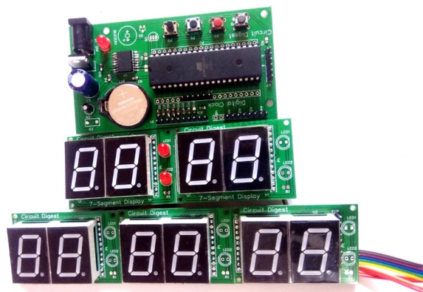
In this Digital Clock Project, ten common anode 7-segment displays of 0.8-inch are used to display time and date. Here seven segment displays are used to show hour, minute, date, month and year. Our PCB design also has options to display seconds and temperature, which can be displayed by adding more display units.
Components Required
- ATmega16 AVR Microcontroller
- DS3231 RTC IC
- Common anode 0.8 inch Seven Segment display (its bigger then common size display (0.56 inch)
- Push button
- Button cell 3v
- 7805 voltage regulator
- 1000uf Capacitor
- Buzzer (optional)
- Transistors BC547 and BC557
- 10uf Capacitor
- 100 Ohm resistor
- 1k resistor
- 10k resistor
- PCB Board
- Jumper wires
- Burgstips
- Power supply adaptor
User may also use Atmega32 it need to be configured in compiler before generating hex.
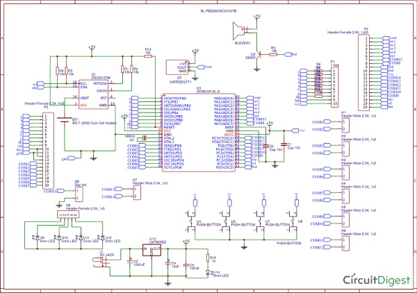
Circuit Diagram and Explanation
There are two parts of this Digital Wall Clock Circuit, one is display part which has 5 pairs of 7-segments on five different PCB boards and another is controlled Unit part which is responsible for fetching time from RTC chip and send that data and time to 7-segment display. As we have used 10 seven segment displays so we cannot connect each display with a separate IO port. So here multiplexing technique is used to connect multiple seven segments using fewer pins of microcontroller.
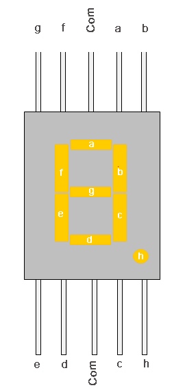
LED pins a,b,c,d,e,f,g,h of seven segment display is connected to PORTB of atmega16 parallel. Here we have used 10 seven segment displays so we need 10 control pins which are connected at PORTD, PORTA and PORTC.
RTC DS3231 having an internal crystal is connected to PORTC’s SDA and SCL pin because this chip works on I2C communication. Interfacing method of this chip is the same as DS1307. We have used DS1307 with Arduino, Raspberry Pi and 8051 MCU. Same code can be used for both DS3231 and DS1307.
Two 10k pull-up resistors are connected on SDA and SCL line. A 3v coin cell is used to power the RTC chip to keep track of time even when the main power supply is off. Whenever power comes back again time will start displaying on seven segment display. Now we have some push buttons for setting time at PORT A, complete process is explained in the video given at the end. A 5v voltage regulator is used to convert input voltage to 5v. All the connections are shown in the circuit diagram below:
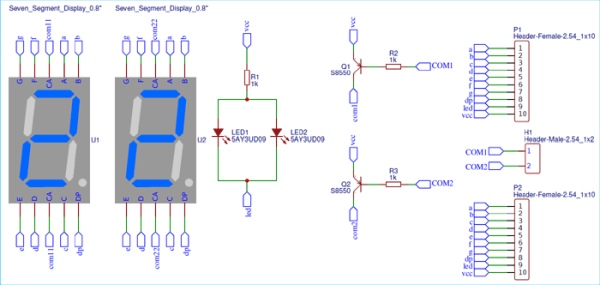
For one display board, two seven segment displays and 2 LED are used. So here we have five different display boards to display Time in Hours and minute (HH-MM), and date in DD-MM-YY.
PCB Design and fabrication for the Digital Clock
For this Atmega16 based wall clock project, we have designed two PCBs. One is for Control unit which is used to control all the operations of the project and second part is for displaying the time and date on seven segment displays. Display part contains five pairs of 0.8 inches seven segment display. So by assembling 5 pieces we have the complete Digital Clock. To multiplex 7-segment displays, Data line of the 5 PCBs will be connected to the same port of control unit and control line is connected different pin of the control unit.
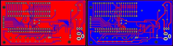
Below are the top and bottom views of PCB layouts of one Display board which consists two seven segment displays:
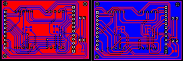
Below are the top and bottom views of Control Unit PCBs
Here we are attached Gerber file for both the boards:
Ordering the PCB using PCBGoGo
There are many PCB fabrication services are available online, but as I used PCBGoGo previously in one of my other projects, I found it cheap and hassle-free as compared to other vendors.
Here are the steps to order PCB from PCBGoGo:
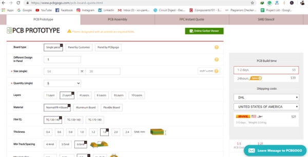
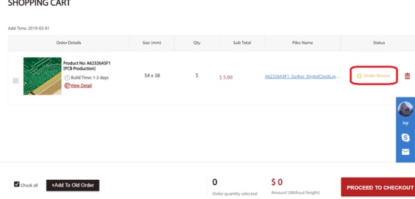
Step 1: Get into www.pcbgogo.com, sign up if this is your first time. Then, in the PCB Prototype tab enter the dimensions of your PCB, the number of layers and the number of PCB you require.

Step 2: Proceed by clicking on the Quote Now button. You will be taken to a page where to set few additional parameters if required like the material used track spacing etc. But mostly the default values will work fine. The only thing that we have to consider here is the price and time. As you can see the Build Time is only 2-3 days and it just costs only $5 for our PSB. You can then select a preferred shipping method based on your requirement.
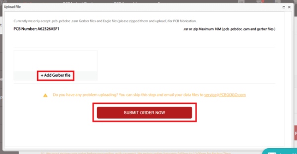
Step 3: The final step is to upload the Gerber file and proceed with the payment. To make sure the process is smooth PCBGOGO verifies if your Gerber file is valid before proceeding with the payment. This way you can sure that your PCB is fabrication friendly and will reach you as committed.
Now PCBGoGo will take some time around 10 min to 1 Hour to review your Gerber file. After completion of the review, you can proceed with the payment.
Assembling the PCB
After the board was ordered, it reached me after some days though courier in a neatly labeled well packed box and like always the quality of the PCB was awesome. I am sharing few pictures of the boards below for you to judge.
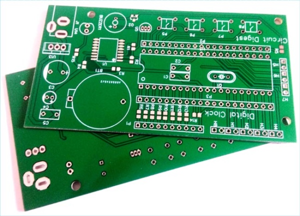
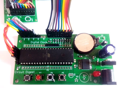
I turned on my soldering rod and started assembling the Board. Since the Footprints, pads, vias and silkscreen are perfectly of the right shape and size I had no problem assembling the board. The board was ready in just 10 minutes from the time of unpacking the box.
Few pictures of the board after soldering are shown below.
Testing the Digital Clock
Complete code is given at the end of this tutorial, just connect the PCBs as shown in the circuit diagram and upload the code into Atmega16. And you will see time and date appearing on the ten Seven segments displays.
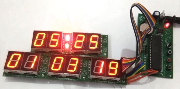
The time and date can be set using the four push button on the control unit as demonstrated in the video given below.
Code
/*
- DigitalClock.c
* - Created: 2/28/2019 3:34:56 AM
- Author: Saddam
*/
include
define F_CPU 8000000UL
include
include
int day=6,dd=1,mm=3,yy=19;
unsigned int sec, min=13, hr=4;
const unsigned int num[]={0X40,0X79,0X24,0X30,0X19,0X12,0X02,0X78,0X00,0X10};
int d0,d1,d2,d3,d4,d5,d6,d7,d8,d9;
volatile unsigned int count,count1;
define digit 13
define dataPort PORTB
define controlPortD PORTD
define controlPortC PORTC
define controlPortA PORTA
define controlPortD_Mask 0x83
define controlPortC_Mask 0x03
define controlPortA_Mask 0x7F
define segmentOff -1
define sw PINA
define set 4
define ok 3
define up 2
define down 1
define setEvent (sw & (1<<set))
define okEvent (sw & (1<<ok))
define upEvent (sw & (1<<up))
define downEvent (sw & (1<<down))
define LEDPORT PORTA
define secLed 5
define BUZPORT PORTD
define buzzer 7
char blinkFlag;
volatile char onFlag=0x00;
define timeFormat 24
enum
{
hour=1,
minute,
date,
month,
year,
};
char segOn[12]={0x04,0x08,0x10,0x20,0x40,0x80,0x40,0x80,0x10,0x20,0x04,0x08};
void display();
void updateTime();
ISR(TIMER1_OVF_vect)
{
display();
TCNT1 = 64000;
}
void selectSeg(int count)
{
if(count < 5)
{
controlPortA&=controlPortA_Mask;
controlPortC&=controlPortC_Mask;
controlPortD&=controlPortD_Mask;
controlPortD|=segOn[count];
}
else if(count == 5)
{
controlPortA|=segOn[count];
controlPortC&=controlPortC_Mask;
controlPortD&=controlPortD_Mask;
}
else if(count == -1)
{
controlPortA&=controlPortA_Mask;
controlPortC&=controlPortC_Mask;
controlPortD&=controlPortD_Mask;
}
else
{
controlPortA&=controlPortA_Mask;
controlPortC&=controlPortC_Mask;
controlPortD&=controlPortD_Mask;
controlPortC|=segOn[count];
}
}
void segment(int count, int seg)
{
if(blinkFlag == seg)
{
if(onFlag)
selectSeg(segmentOff);
else
selectSeg(count);
}
else
{
selectSeg(count);
}
}
void display()
{
count1++;
if(count1>400)
{
count1=0;
onFlag=!onFlag;
}
count++;
if(count>digit)
count=0;
switch(count%digit)
{
case 0:
segment(count,minute);
dataPort=num[d0];
break;
case 1:
segment(count,minute);
dataPort=num[d1];
break;
case 2:
segment(count,hour);
dataPort=num[d2];
break;
case 3:
segment(count,hour);
dataPort=num[d3];
break;
case 4:
segment(count,date);
dataPort=num[d4];
break;
case 5:
segment(count,date);
dataPort=num[d5];
break;
case 6:
segment(count,month);
dataPort=num[d6];
break;
case 7:
segment(count,month);
dataPort=num[d7];
break;
case 8:
segment(count,year);
dataPort=num[d8];
break;
case 9:
segment(count,year);
dataPort=num[d9];
break;
}
}
void timer1_init()
{
// set up timer with prescaler = 8
TCCR1B |= (1 << CS11);
//TCCR1B &= ~(1 << CS10);
//TCCR1B &= (1 << CS11);
//TCCR1B &= ~(1 << CS12);
TCNT1 = 63500;
TIMSK |= (1 << TOIE1);
sei();
}
int bcdtochar(char num)
{
return ((num/16 * 10) + (num % 16));
}
int dectobcd(char num)
{
return ((num/10)<<4) + (num % 10);
}
void RTC_start()
{
TWCR=(1<<TWINT)|(1<<TWSTA)|(1<<TWEN);
while((TWCR&0x80)==0x00);
}
void device()
{
TWDR=0xD0; //RTC write (slave address)
TWCR=(1<<TWINT)|(1<<TWEN);
while(!(TWCR&(1<<TWINT)));
TWDR=0x00; // word address write
TWCR=(1<<TWINT)|(1<<TWEN);
while(!(TWCR&(1<<TWINT)));
}
void RTC_stp()
{
TWCR=(1<<TWINT)|(1<<TWEN)|(1<<TWSTO); //stop communication
}
void RTC_read()
{
TWCR=(1<<TWINT)|(1<<TWSTA)|(1<<TWEN);
while((TWCR&0x80)==0x00);
TWDR=0xD0; //RTC write (slave address)
TWCR=(1<<TWINT)|(1<<TWEN);
while(!(TWCR&(1<<TWINT)));
TWDR=0x00; //RTC write (word address)
TWCR=(1<<TWINT)|(1<<TWEN);
while(!(TWCR&(1<<TWINT)));
TWCR=(1<<TWINT)|(1<<TWSTA)|(1<<TWEN); //start RTC communication again
while ((TWCR&0x80)==0x00);
TWDR=0xD1; // RTC command to read
TWCR=(1<<TWINT)|(1<<TWEN);
while(!(TWCR&(1<<TWINT)));
}
void sec_init(unsigned char d)
{
TWDR=d; //second init
TWCR=(1<<TWINT)|(1<<TWEN);
while(!(TWCR&(1<<TWINT)));
}
void min_init(unsigned char d)
{
TWDR=d; //minute init
TWCR=(1<<TWINT)|(1<<TWEN);
while(!(TWCR&(1<<TWINT)));
}
void hr_init(unsigned char d)
{
TWDR=d; //hour init
TWCR=(1<<TWINT)|(1<<TWEN);
while(!(TWCR&(1<<TWINT)));
}
void day_init(unsigned char d)
{
TWDR=d; //days init
TWCR=(1<<TWINT)|(1<<TWEN);
while(!(TWCR&(1<<TWINT)));
}
void date_init(unsigned char d)
{
TWDR=d; //date init
TWCR=(1<<TWINT)|(1<<TWEN);
while(!(TWCR&(1<<TWINT)));
}
void month_init(unsigned char d)
{
TWDR=d; //month init
TWCR=(1<<TWINT)|(1<<TWEN);
while(!(TWCR&(1<<TWINT)));
}
void yr_init(unsigned char d)
{
TWDR=d; //year init
TWCR=(1<<TWINT)|(1<<TWEN);
while(!(TWCR&(1<<TWINT)));
}
int sec_rw()
{
int g[3];
TWCR|=(1<<TWINT)|(1<<TWEA); //RTC second read
while((TWCR & 0x80)==0x00);
return bcdtochar(TWDR);
}
int min_rw()
{
TWCR|=(1<<TWINT); //RTC minute read
TWCR|=(1<<TWEA);
while((TWCR & 0x80)==0x00);
return bcdtochar(TWDR);
}
int hr_rw()
{
TWCR|=(1<<TWINT)|(1<<TWEA); //RTC hour read
while((TWCR & 0x80)==0x00);
return bcdtochar(TWDR);
}
int day_rd()
{
TWCR|=(1<<TWINT)|(1<<TWEA); //RTC day read
while((TWCR&0x80)==0x00);
return bcdtochar(TWDR);
}
int date_rw()
{
TWCR|=(1<<TWINT)|(1<<TWEA); //RTC date read
while((TWCR & 0x80)==0x00);
return bcdtochar(TWDR);
}
int month_rw()
{
TWCR|=(1<<TWINT)|(1<<TWEA); //RTC month read
while((TWCR & 0x80)==0x00);
return bcdtochar(TWDR);
}
int yr_rw()
{
TWCR|=(1<<TWINT); //RTC year read
TWCR&=(~(1<<TWEA));
while((TWCR & 0x80)==0x00);
return bcdtochar(TWDR);
}
void setTime()
{
RTC_start();
device();
sec_init(0);
min_init(dectobcd(min));
hr_init(dectobcd(hr));
day_init(dectobcd(day));
date_init(dectobcd(dd));
month_init(dectobcd(mm));
yr_init(dectobcd(yy));
RTC_stp();
}
void RTC()
{
RTC_read();
sec=sec_rw();
min=min_rw();
hr=hr_rw();
day=day_rd();
dd=date_rw();
mm=month_rw();
yy=yr_rw();
RTC_stp();
}
char getPara(char count)
{
while(1)
{
updateTime();
if(!upEvent)
{
count1=0;
onFlag=0x00;
count++;
if(blinkFlag == hour)
{
if(timeFormat == 12)
{
if(count>12)
count=0;
}
else
{
if(count > 23)
count=0;
}
hr=count;
}
else if(blinkFlag == minute)
{
if(count>59)
count=0;
min=count;
}
else if(blinkFlag == month)
{
if(count > 12)
count=1;
mm=count;
}
else if(blinkFlag == date)
{
if(mm == 4 || mm == 6 || mm == 9 || mm == 11)
{
if(count > 30)
count=1;
}
else if(mm == 1 || mm == 3 || mm == 5 || mm == 7 || mm == 8 || mm == 10 || mm == 12)
{
if(count >31)
count=1;
}
else
{
int y=2000+yy;
if(y/4 == 0 && y/400 == 0)
{
if(count > 29)
count=1;
}
else
{
if(count > 28)
count=1;
}
}
dd=count;
}
else if(blinkFlag == year)
{
if(count >99)
count=0;
yy=count;
}
_delay_ms(200);
}
else if(!(downEvent))
{
count–;
if(blinkFlag == year)
{
if(count<0)
count=99;
}
_delay_ms(100);
}
else if(!okEvent)
{
_delay_ms(1000);
return count;
}
}
}
void settingTime()
{
blinkFlag=1;
hr=getPara(hr);
blinkFlag++;
min=getPara(min);
blinkFlag++;
dd=getPara(dd);
blinkFlag++;
mm=getPara(mm);
blinkFlag++;
yy=getPara(yy);
blinkFlag=0;
}
void updateTime()
{
d0=min%10;
d1=min/10;
d2=hr%10;
d3=hr/10;
d4=dd%10;
d5=dd/10;
d6=mm%10;
d7=mm/10;
d8=yy%10;
d9=yy/10;
}
int main(void)
{
unsigned long int Time;
DDRB=0xff;
DDRA=0xE0;
PORTA=0x1E;
DDRD=0xff;
DDRC=0xff;
timer1_init();
while(1)
{
RTC();
updateTime();
_delay_ms(500);
LEDPORT|=1<<secLed;
_delay_ms(500);
LEDPORT&=~(1<<secLed);
if (!setEvent)
{
settingTime();
setTime();
}
}
}
Video
Source: Digital Wall Clock on PCB using AVR Microcontroller Atmega16 and DS3231 RTC
- What RTC chip is used in the project?
The DS3231 RTC IC is used, which has a highly accurate internal crystal. - Can Atmega32 be used instead of Atmega16?
Yes, Atmega32 can be used but it needs to be configured in the compiler before generating the hex. - How many seven segment displays are used to show time and date?
Ten common anode 0.8-inch seven segment displays are used, arranged as five boards with two displays each. - How is the DS3231 connected to the microcontroller?
DS3231 is connected to PORTC SDA and SCL pins and uses I2C communication with two 10k pull-up resistors on SDA and SCL. - How are multiple seven segment displays driven with fewer MCU pins?
Multiplexing is used: segment lines connect to PORTB and control lines for each display are on PORTD, PORTA, and PORTC. - Does the RTC keep time when main power is off?
Yes, a 3V coin cell powers the RTC to keep track of time when main power is off. - Are Gerber files provided for the PCBs?
Yes, Gerber files for both the control unit and seven segment display board are attached in the project. - How is the PCB ordered as suggested in the article?
The article describes ordering from PCBGoGo: enter PCB specs, quote, upload Gerber files, then pay after their review. - How is time set on the clock?
Time and date are set using the four push buttons on the control unit, with the process shown in the project video. - Is source code provided for the project?
Yes, the complete code is given in the tutorial for Atmega16 to interface with DS3231 and drive the displays.