@ Erhan brother Atmega8 prepared with the application had shared (Atmel Atmega8 Nokia 6100 LCD (pcf8833) application) I In addition to the helpful one more example’ll share the codes and microchip dspıc33fj128gp both the… Electronics Projects, dsPIC33FJ128GP Nokia 6100 LCD driver circuit ATmega168 “avr project, dspic projects, microcontroller projects, “
@ Erhan brother Atmega8 prepared with the application had shared (Atmel Atmega8 Nokia 6100 LCD (pcf8833) application) I In addition to the helpful one more example’ll share the codes and microchip dspıc33fj128gp both the Atmel ATmega168 microcontroller can be used with.
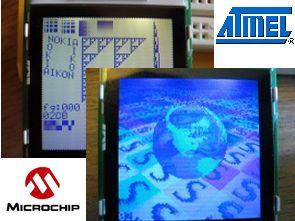
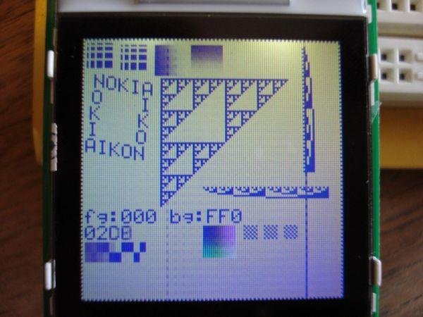
Nokia 6100 test circuit image;
NOKIA 6100 LCD DRIVER CIRCUIT
Written by Dan Stahlke, [email protected], http://www.stahlke.org/dan/nokialcd The driver was based upon an example written by SparkFun, and the font was taken from the KS0108 library (http://en.radzio.dxp.pl) and is (c) Rados³aw Kwiecieñ, [email protected] This code can be used for any purpose, free or commercial, but there is no warranty implied whatsoever.
This package contains drivers for the Nokia 6100 LCD. The driver has only been tested with the new Epson unit from SparkFun (Chinese clone, red tab on protective cover, green PCB with brown traces). It should work with the Philips or the older Epson chips too but will inevitably need some fixes (in particular the LCD_Y_OFFSET variable should probably be set to zero). If you get it to work with other chipsets please let me know. You may also have to edit the contrast setting which is defined in the LCDInitController function
This code has been tested with the ATmega168 and dsPIC33FJ128GP chips, and makefiles are included for each. The makefiles are a bit Linux-centric and may need some editing. Alternatively, you could easily bring this code into the Microchip or Atmel IDE. In this case you must make sure to pass the “-DEPSON” or “-DPHILIPS” flag to the C compiler to tell the code which LCD chipset you are using.
If you want to port this code to a new MCU all you need to do is provide code to initialize the ports and to do a 9-bit SPI transfer. Look in the sysconfig-*.c files for examples.
The graphics routines you get basically consist of functions for setting individual pixels, filling rectangles, drawing text, and drawing raster blocks. There is no code for diagonal lines or circles (when is the last time you have actually seen this functionality used on an LCD?). Feel free to add more routines and send me patches. The code in demo_testpattern.c is probably a good way to learn how to use this driver.
See the end of this file for a wiring diagram. You don’t really need to use the MISO pin. This is used for reading from the display, which is not currently implemented. If you leave this out make sure to keep the 1k resistor between MOSI and the LCD DIO pin. The DIO pin is both an input and an output, and the resistor provides safety in the case where both the LCD and the MCU are outputting at the same time.