
Summary of Enhancing An FM Transmitter’s Firmware using ATmega48
This article details a project to rewrite the firmware of PLL FM transmitters using AVR microcontrollers, specifically an ATmega48 paired with a BH1415 chip. The process involves identifying the hardware via PCB inspection, stabilizing power for ISP programming, and re-flashing the locked memory from scratch. Key components include the microcontroller, FM modulator, display, buttons, and programmer interface.
Parts used in Enhancing An FM Transmitter’s Firmware:
- ATMega48 microcontroller
- BH1415 PLL FM transmitter chip
- 3.5 digits display
- 2 buttons
- 6-way ISP header footprint
- AVRISP programmer
- 7-segment display interface resistors
- External 5V power source
This hack is about rewriting the firmware of PLL FM transmitters based on AVR microcontrollers to add more functionalities. They’re commonly available on eBay from various sellers and for prices ranging from $40 to $80, depending mostly on the RF output power.
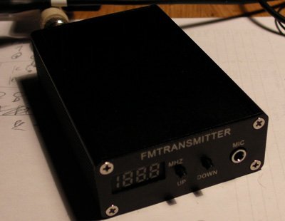
If you don’t know if a similar transmitter is based on an AVR or not, don’t hesitate to ask the seller for a (good) picture of the PCB. They’ll certainly accept as there isn’t anything secret about the design.
Most of the transmitters I came across in that price range are based on AVRs. Those that are able to read audio files from SD cards or USB drives probably host an obscure microcontroler capable of handling those functionalities easily (not supported here !).
The transmitter I used to test this hack relies on a ATMega48 micro and a BH1415 PLL FM transmitter chip (complete datasheet).
The user interface is made of a 3.5 digits display and 2 buttons (normally used to, you guessed it, increment and decrement the frequency).
A 3-wire link between the micro and FM modulator chip allows it to configure the frequency and transmission type (mono or stereo).
I hooked up my knockoff AVRISP programmer to the convenient 6-way ISP header footprint on the PCB, powered up the transmitter and checked if I could read the device signature.
Surprisingly, even with the slowest clock speed, the 3 bytes were changing at each read. That meant the power supply wasn’t stable enough, or the ISP lines were catching the RF stage’s output.
I then removed the 12V main input and only powered the AVR with an external and well rectified 5V source. The signature finally showed correctly !
The next step was to see if I could at least do a backup of the original firmware by reading the flash memory contents. Unfortunately, it was locked, so I had no other choice than erasing the AVR and writing everything from scratch.
First, I had to know how the AVR was connected to the rest of the circuit.
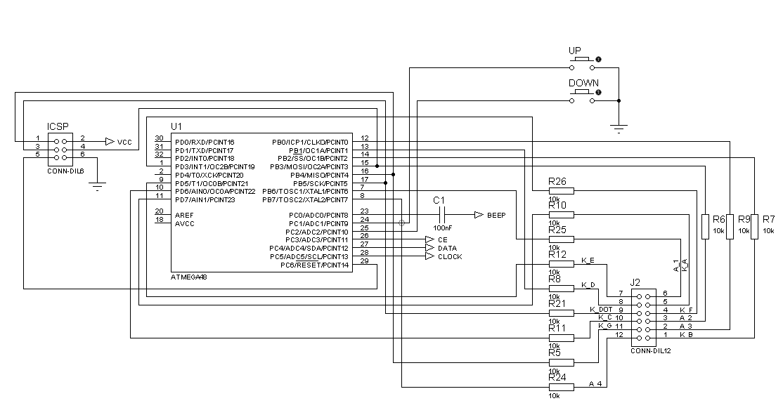
Nothing complicated, it was just a matter of following traces and beeping a few hidden ones. The 7-segment display interface (on port B and D) has obviously been routed to simplify the board layout. The BH1415 interface and button inputs are on port C.
Nothing can really go wrong as all the signals for the LEDs of the display go through 1k resistors (twice, in fact), and the BH1415 is immune to bad data.
For more detail: Enhancing An FM Transmitter’s Firmware using ATmega48
-
How can I identify if a transmitter uses an AVR microcontroller?
Ask the seller for a good picture of the PCB since there is nothing secret about the design. -
Does this hack support transmitters that read audio files from SD cards or USB drives?
No, those units likely use obscure microcontrollers not supported by this method. -
Why were the device signature bytes changing during the initial read attempt?
The power supply was unstable or the ISP lines were picking up RF stage output. -
What solution resolved the unstable power issue during programming?
Remove the 12V main input and power the AVR with an external rectified 5V source. -
What happened when attempting to backup the original firmware?
The flash memory was locked, requiring the user to erase the AVR and write everything from scratch. -
Which ports control the display and button inputs on the circuit board?
The 7-segment display is routed to port B and D while the BH1415 interface and buttons are on port C.
