Summary of ESP32 Robot Using Servos
This article details the construction of a lightweight ESP32-based robot car using continuous rotation servos. The project leverages the TTGO T-Beam board's integrated battery and charging capabilities to simplify power management. The build involves creating a custom chassis from perspex, fabricating a modified veroboard for simplified servo control wiring, and implementing a web server interface for remote operation via an OLED display.
Parts used in the ESP32 Robot Using Servos:
- 4 x Continuous rotation Servos
- 4 x Wheels that fit on the Servos
- 1 x strip of 5 x Neopixels
- 1 x ESP32 with built-in rechargeable battery or external battery
- 1 x Small piece of perspex for chassis
- 1 x small piece of veroboard
- Wire and mini jst socket connector
- 4 x Servo Headers
- Plastic circuit board standoffs
I have been experimenting using different ESP32 development boards, recently I ordered of the TTGO T-Beam variety which come with a Battery socket to add your own 18650 Lipo, this really takes some of the power regulation complexity out of building a small robot, as it has the battery and charger circuit in place already.
However to directly drive something from this board it needed something low powered, so I decided to add some continuous rotation servos I have had for a while.
The ESP32 board I used here has a lot of functionality including Lora radio and GPS, which may be useful in the future, but you can get ESP32 boards without these extras which make the board a bit smaller and still come with the 18650 battery holder.
So let’s start talking about the build.
Supplies:
4 x Continuous rotation Servos
4 x Wheels that fit on the Servos
1 x strip of 5 x Neopixels if you want to add them.
1 x ESP32 with ideally built in rechargeable battery, or an ESP32 with an external battery.
I bought mine from Lilygo Aliexpress which shipped way quicker than I expected the one i used can be found here https://www.aliexpress.com/item/32967228739.html?spm=a2g0s.9042311.0.0.206f4c4dXaqAU9
1 x Small piece of perspex, that can be cut and drilled to form chassis.
1 x small piece of veroboard
some wire, and I used a mini jst socket as a connector, but this could just be soldered.
4 x Servo Headers, so you can just plug the servos in to the connector veroboard
Some plastic circuit board standoffs.
Step 1: Building the Chassis
I wanted a real basic chassis that any body could make using some perspex or plastic, even an old plastic lunch box or takeaway could potentially be used.
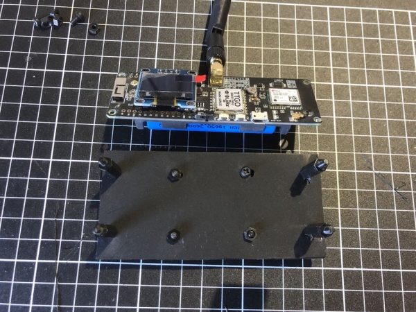
I cut a piece of perspex out a little wider than the ESP32 board, but about the same length, I then marked where I would want to add the 4 holes to mount the ESP32 using circuit board standoffs.
Attaching the Servos
I positioned the Servos so that they were all orientated the same way, so when wired up they would drive the same direction. I used some plastic glue to put these in place and added some more standoffs to aid in holding them.
I drilled holes for the servos wires to go through the base of the chassis so they could be plugged into the small veroboard I used which I will detail later on.
I bundled up the servo excess wiring the best I could and used a couple of small cable ties to hold them in position.
Covering it all up
As a final step I covered it all in with a piece of perspex the same size as the first piece I cut. I drilled holes for the extra standoffs and added standoff screws to hold it all in place.
I was surprise how light this once together was in weight, much lighter than my motor based one I made the previous week.
Step 2: Making a Custom Veroboard
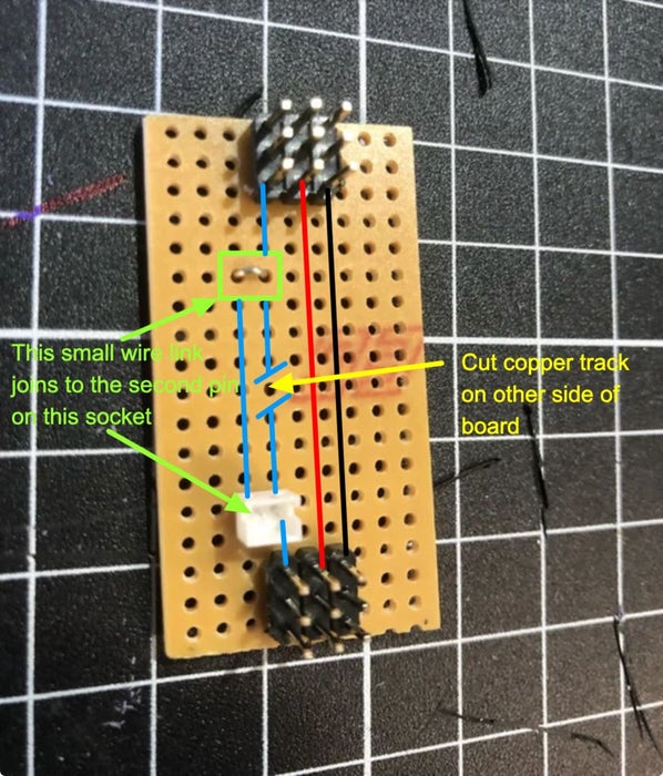
I wanted to make a small board that would allow me to plug my ESP32 into the board and be easy to remove when needed. So I created it as show in the photographs, I added some header pins so I could plug in the Servos and later a neopixel strip.
I also added 2 small jst sockets I had some of so I could use these for power from the ESP32 and also to provide the Servo signal connections.
I cut one of the copper tracks on the underside of the board, so that the signal pin to each servo was different, I then used a small wire connector to move it by the wire by one track so the two jst pins would connect with one side or the other.
As there were two servos on each side of the vehicle I used the board to connect the two servos each side to each other, so i could run the left hand side servos or right hand side ones with a single servo connection, to each side. All I am doing here is connecting the connections together for each side to simplify the amount of wiring needed.
I allowed the Vcc and GND connection to connect all the way across the veroboard via the copper tracks, however I cut the signal line so I could control the different sides I wanted to drive independently.
Step 3: The Wiring
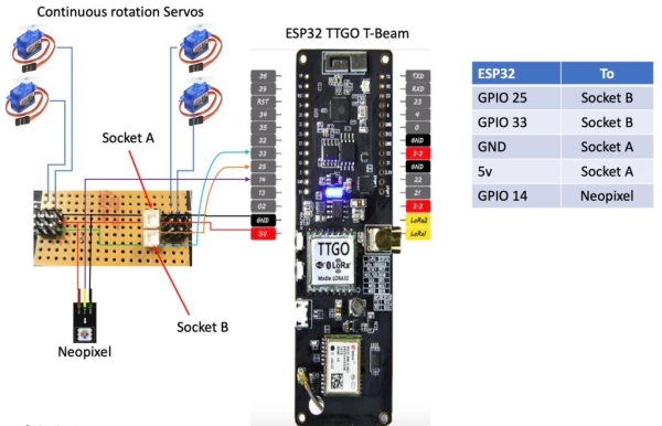
To wiring diagram here shows the connections and how with as few wires as possible I connected the Servos and Neopixel strip.
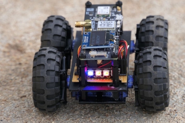
Step 4: Putting It All Together
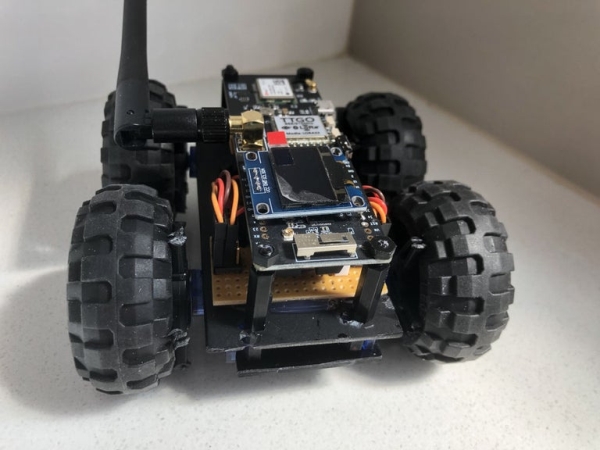
Once I had everything wired I fitted the custom veroboard, and added the ESP32 to the chassis, it all fitted well.
The wiring was mostly concealed and hidden and sides could easily be added and a top to fully enclose the ESP32.
Step 5: Controlling and Testing
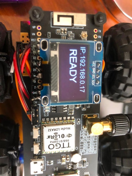
I wanted some simple controls and found that at the website https://randomnerdtutorials.com/ they provided a good example how to run a webserver and have controls displayed so you could get the robot car to drive around. I modified the example to use servos instead of motors, and added code to use the neopixel strip, as well as to display on the Oled screen the IP address I would need to connect to so I could control the robot.
Step 6: Code for the ESP32
Here I attach the code which can be modified for your own purposes, full credit goes to randomnerdtutorials which form the basis of what I have here. I would highly recommend buying the course they have on the ESP32, it takes you through lots of the complexities using the ESP32, with some really good example projects.
I hope this has been useful to others trying to get up to speed in using the ESP32 for robotics.
You can follow me on twitter to see more of what I do here @elliotpittam or you can visit my website for other information. www.inventar.tech
Source: ESP32 Robot Using Servos
-
What board was used for the ESP32 robot?
The TTGO T-Beam variety was used because it includes a battery socket and charger circuit. -
How were the servos connected to simplify wiring?
A custom veroboard was created to connect two servos on each side together so they could be driven by a single connection per side. -
Can this robot be controlled remotely?
Yes, a webserver example was modified to allow control via a browser using IP address displayed on an OLED screen. -
What material was used to build the chassis?
A small piece of perspex was cut and drilled to form the base and top cover of the chassis. -
Why were continuous rotation servos chosen?
They were selected because the ESP32 board needs low power to drive them directly without complex motor drivers. -
How is the power regulated in this project?
The TTGO T-Beam board handles power regulation complexity by including a built-in battery and charger circuit.