Summary of Explore AVR assembly language
The article explains writing AVR assembly to blink the Arduino Uno onboard LED by toggling PB5 (digital pin 13). It covers registers (DDRB, PORTB, PINB), using a device definition file (m328pdef.inc), register aliases, delay loops with 8/16-bit values, assembling with avra on Linux, and uploading the generated .hex using avrdude. The provided blink.asm toggles PB5 with nested loops to produce ~1s blink intervals.
Parts used in the AVR Blink Project:
- Arduino Uno board (ATmega328P)
- Computer (Linux recommended for avra example)
- avra assembler (Avra)
- m328pdef.inc device definition file
- blink.asm assembly source file
- avrdude programmer utility
- USB cable to connect Arduino to computer
Let’s explore the AVR microcontroller along with its assembly language. We’ll develop an assembly program designed to make the LED on an Arduino Uno board flash on and off.
Story
Assembler programming operates at the hardware level, employing a concise set of instructions to execute mathematical operations and manipulate binary data. At this stratum, our commands directly control the state of circuits.
Avrasm2, developed by Atmel (now MicroChip), is the designated program for their AVR product line. Installation takes place on Windows systems during the setup of MicroChip Studio IDE or the older Atmel Studio Suite. Comprehensive documentation for AVRASM2 is available online.
For this particular project, I will utilize the Avra assembler on a Linux environment. Our approach involves a text editor for composing the source code and the command-line interface (CLI) within the terminal window. It’s important to avoid using applications like MSWord, WordPad, or OpenOffice, as they can introduce hidden formatting characters to the text.
Let’s Code
We will employ the following program for our task. Roughly every second, the sixth pin on the microcontroller chip’s PORTB will alternate the state of the LED on the Arduino Uno board, causing it to blink on and off.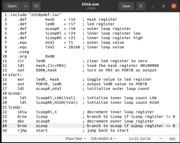
Arduino Output Circuit
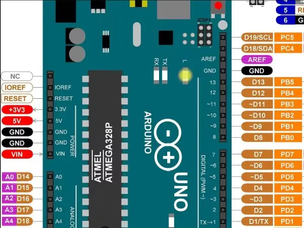
At the outset of this project, you’ll notice an image of the Arduino Uno placed at the top. Direct your attention to PB5, which corresponds to pin 13 situated at the right edge of the board. Notably, the Uno features a built-in LED circuit.
The instructions within our program will be translated into sequences of 0’s and 1’s that actively regulate voltages. This control extends to determining the pins designated for output. Positioned at memory address 0x25, PORTB comprises 8 distinct memory circuits, functioning as a conduit for generating the binary representation of the PORTB value. On the other hand, PINB functions as an input, perceiving the voltage states existing at PORTB. Additionally, DDRB assumes the role of the Data Direction Register associated with PORTB, residing at memory address 0x24.
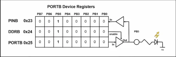
Presented here is a schematic outlining the internal circuitry of the microcontroller chip. Positioned as the initial pin of PORTB, PB0 corresponds to pin D8 on the Uno Board. Notably, PB5 is interlinked with the pre-existing LED circuit. In the context of the Arduino IDE, we can activate PB5 as an output using the command pinMode(LED_BUILTIN, OUTPUT).
In scenarios where output pin PB5 on the Arduino Uno is governed by DDRB = 1, the output circuitry pertinent to that specific pin becomes operational. Conversely, when DDRB = 0, the circuitry permits the pin to establish a connection with the PINB register, thus configuring it for voltage input.
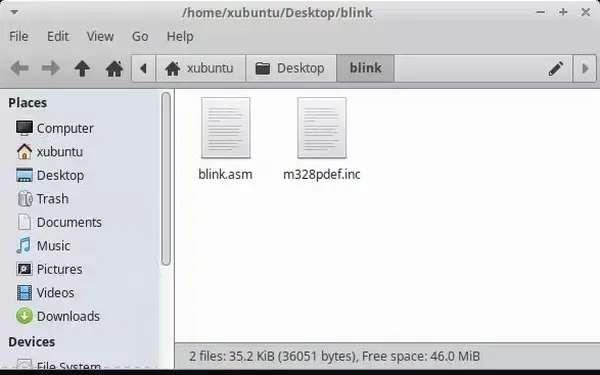
Preparation
Retrieve the attached blink.asm and m328pdef.inc files from this project. Establish a fresh directory and relocate the two aforementioned files into this newly created folder.
Edit blink.asm
The AVR assembly language comprises a concise set of instructions. Terms like “inc,” “dec,” “clr,” or “ldi” hold specific meanings within the assembler program and can only be used for their designated purposes, such as increment, decrement, load immediate, and so on.
In our program, we make use of DDRB and PORTB. But where do these terms originate, and what do they signify? Surprisingly, they aren’t inherent to the Assembly language itself.
Assembly language empowers us to substitute these terms with corresponding values. To facilitate this, a definition file exists for the Atmega328p, the microcontroller utilized in the Arduino Uno. A slightly modified definition file has been created for the Atmega8 chip.
You’ll find the definition file pertinent to our exercise attached. Open this file using a text editor and search for DDRB and PORTB. Upon doing so, you’ll encounter directives that establish equivalencies between different elements. For instance, if you look up PB5, you’ll discover:
.equ PB5 = 5 ; For compatibilityThe significance of this line to the assembler is that when it encounters PB5 within the program, it should interpret it as the value 5. We will revisit this aspect later in our project.
The registers r0 to r31 are situated close to the core of the processor. Each of these registers functions as an 8-bit storage unit, enabling the controller to execute mathematical operations. You can envision them akin to 8-bit abacuses, with individual bits replacing the traditional beads.
Following this, we proceed to define certain terms—labels—that assist us in recollecting and comprehending the code. This enhances the logical structure of our program. For instance, r16 is assigned the label “mask,” holding a value that we will employ to activate the thirteenth pin on the Atmel MCU device.
As for r17, it governs whether the LED is in an active or inactive state, hence we name it “ledR.” Meanwhile, r18, r24, and r25 store numerical values that will decrement to introduce a delay. By assigning these registers names within our program, we’re making an effort to render our code more accessible and understandable for us humans.
Loop Values
The values designated for the delay are denoted as “oVal” and “iVal.” When the assembler comes across these labels in our assembly code, it will refer to the memory locations where these assigned numbers reside.
But wait a moment! Keep in mind that 8-bit numbers can only reach up to 255. So, how do we manage calculations involving larger values?
The AVR microcontroller is equipped to handle numbers with 16 bits. This means we can perform operations like counting, multiplication, and division with numbers that go as high as 65025. Later in the program, we will encounter special reserved keywords like “HIGH” and “LOW” that play a role in implementing 16-bit mathematics.
Specifically, “oVal” corresponds to the decimal value 71, while “iVal” represents decimal 28168. As a result, the delay values translate to:
.equ    oVal    = 71        ; outer loop value
.equ    iVal    = 28168     ; inner loop value
Our aim is to have the Arduino perform a countdown to zero over the course of approximately one second. To achieve this, you can conduct a Google search for AVR Assembly and these specific numbers. Through this search, you’ll discover comprehensive calculations detailing the time it takes for the commands to execute.
- How does the program toggle the Arduino LED?
It toggles the PB5 bit by eor ledR, mask and writes ledR to PORTB, causing the LED on pin 13 to alternate. - Can I assemble the code on Linux?
Yes, the article demonstrates using the Avra assembler on Linux with the command avra blink.asm. - What file defines DDRB, PORTB, and PB5 names?
The m328pdef.inc device definition file provides definitions for DDRB, PORTB, and PB5. - How is PB5 configured as an output?
By loading mask with (1<<PB5) and executing out DDRB, mask to set PB5 as output. - How are the delay loops implemented?
Nested loops use oVal in an 8-bit outer register and iVal as a 16-bit inner count (LOW/HIGH) decremented until zero. - What command uploads the hex to the Arduino?
Use avrdude with parameters like avrdude -p atmega328p -c arduino -P /dev/ttyACM0 -U flash:w:count.hex:i as shown. - Does the article show how to produce the hex file?
Yes, assembling with avra generates blink.hex in the source directory. - What registers are aliased for this program?
Aliases include mask=r16, ledR=r17, oLoopR=r18, iLoopRl=r24, and iLoopRh=r25.