Summary of Fast, Portable and Affordable Oscilloscope and Inductance Meter
This project, multiScope, hides an STM32-based oscilloscope and inductance meter inside a toy-car-like enclosure. It samples signals up to 1.7 MS/s, measures inductances >100 µH (~10% precision), displays analog/digital waveforms, reads temperature/pressure, and shows voltage, frequency, and duty cycle. The build uses a STM32F103 "blue pill", a 2.4" TFT touchscreen, supporting electronics for power and attenuators, and an LM339-based inductance circuit. Software uses Arduino IDE with Arduino STM32 support and a patched TFT/Wire library.
Parts used in the multiScope:
- STM32F103C8T6 minimal dev. board (blue pill)
- 3.3V USB/Serial adapter (FT232RL or similar)
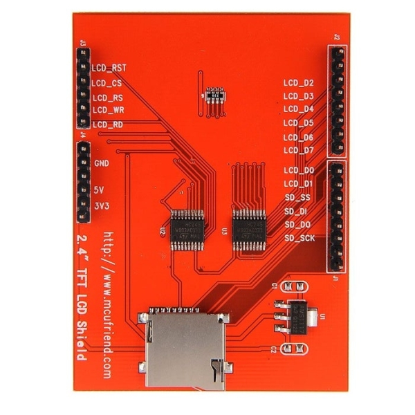
- 2.4 TFT LCD touch screen display
- Box or enclosure (3D-printed, toy, or other)
- 6-9V battery (example: 7.2V Li-ion)
- Small main power switch
- 2x 2.2K resistor
- LM7805 5V regulator
- LM339 comparator IC
- 330R resistor
- 150R resistor
- 1uF ceramic capacitor
- 1N4007 diode
- 2x3 female header socket (for attenuators)
- Additional resistors and trimpots for attenuators
When turned off, it looks like an ordinary toy car that would entertain a kid for hours, but actually it is an oscilloscope kit in disguise!
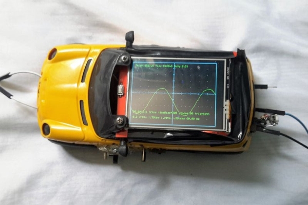
The idea and also part of the code for this project came from another scope called STM-32-O-Scope (aka pigScope), which uses a more powerful Arduino cousin called STM32. I originally posted my version on hackaday, but now I’ve deciced to bring it here too, so it may help more people who don’t have a commercial oscilloscope and also becase there’s a contest happening 😉
I use this tool daily to watch signals or as a second voltmeter and also to measure inductance of home-wound inductors. As the code is open, you may add, remove or improve features according to your needs.
As it’s more than just an oscilloscope and “oscilloscope and inductance meter” is too cumbersome, I named this little guy multiScope. Here’s what it currently does:
- Measure inductances greater than 100uH with 10% precision
- Display analog or digital signals with up to 1.7MS/s sampling rate
- Temperature and pressure sensing (an extra feature)
- Displays voltages, frequency and duty cycle
Step 1: Materials
The core parts for the oscilloscope:
- STM32F103C8T6 minimal dev. board (aka “blue pill”), buy one like this STM32F103C8T6 min. dev. board
- 3.3V USB/Serial adapter (FT232RL or something like that)
- 2.4 TFT LCD touch screen display (the display library I used was adapted to the model of the picture, but with some changes in code, you might be able to use others). Example link: 2.4″ TFT LCD Shield on eBay
- A box or enclosure (may be something 3D-printed, an old box you have or even a plastic toy)
- 6-9V battery (I used 7.2 li-ion as it lasts very long)
- Small switch (main power switch)
- (2x)2.2K Resistor
- LM7805 (5V regulator)
Parts for the inductance meter:
- LM339 (comparator IC)
- Resistors: 330R, 150R
- 1uF ceramic capacitor (the higher the precision, the better)
- 1N4007 (common diode)
Parts for attenuators :
- 2×3 female header socket
- Resistors: how many will depend on how much attenuation you need, but they are regular resistors and trimpots.
Step 2: Add STM32 Support to the Arduino IDE
Before building our hardware, let’s setup our development environment. Here, standard Arduino IDE was used with an add-on called Arduino STM32. The guys who made it also host a forum called Arduino for STM32 that is not so beginner oriented as the Arduino forum, but people can discuss things related to the STM32 board family and also share their projects. There’s even a page with other oscilloscopes based on pigScope too, from which I’ve learned many things and maybe you will too.
OK, so do the following:
- Make sure you have a compatible IDE version. They recommend 1.6.9, but I used 1.8.1 without any problem
- Install Arduino SAMD Boards package with the Arduino Boards Manager (in case you don’t know, it’s a tool inside the Arduino IDE)
- Download or clone Arduino STM32 into the Arduino/hardware folder
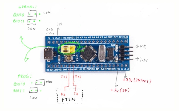
- Open the IDE, select your board (Generic STM32F103C series for blue or red pill) and Serial as Upload Method to program using the USB-Serial adapter
- Connect the board by following the little sketch. You may test it with the ordinay Blink code, just note that the onboard led is on PC13. Every time you upload code, you will have to change the position of the first jumper to switch between Run and Program modes before powering or resetting the board
Step 3: A Quick Arts Class
Once we’re sure the blue pill is working, let’s proceed to the display. I won’t cover the placement of parts in detail because it will depend on the enclosure you’ve chosen. Be creative and put them where you think it’s best.
The patched TFT library contains code that might not work well with the default Wire library due to pin conflict, so let’s edit a few lines to avoid trouble:
- Go to Arduino\hardware\Arduino_STM32\STM32F1\libraries\Wire
- Open Wire.h with a text editor you like and look for #define SDA
- Make it like this:
#define SDA PC15
#define SCL PC14
- Save the file. Now SDA is on PC15 and SCL is on PC14.
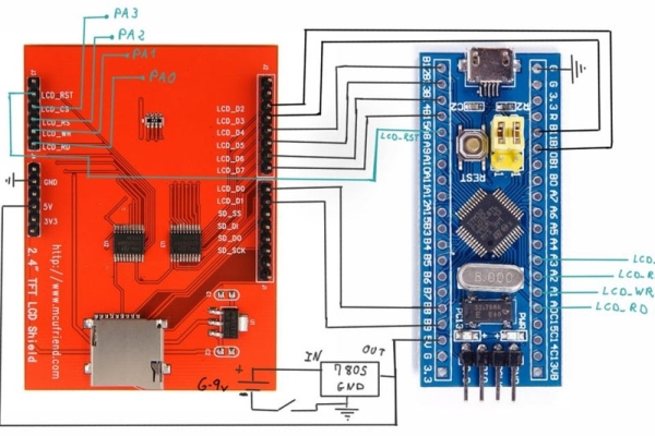
Now, do the display wiring as described in my drawing. After it’s finished, download multiScope_patched_librarires.zip and extract to your libraries folder. To test it, upload lcd_touch_paint.ino. The pins are already adjusted. All you need to do is set your inner artist free.
Step 4: To Measure Inductance
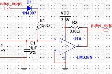
Now, we’re going to build the inductance meter circuit. It’s a very simple one, and works in a somewhat similar way to ultrasound sensors: STM32 sends a “trigger” pulse to pulse_in and receives another trough pulse_out, from which we extract frequency (and thus inductance) information. This site explains the schematic and the physics principles in detail if you’re interested.
You should connect pulse_in to PB3 and pulse_out to PB4. The unknown inductor of the schematic is the one we want to measure. Solder some alligator clips or female jumpers if you want.
Source: Fast, Portable and Affordable Oscilloscope and Inductance Meter
- What microcontroller board is used in the multiScope?
The project uses the STM32F103C8T6 minimal development board (blue pill). - Can multiScope measure inductance?
Yes, it measures inductances greater than 100uH with about 10% precision. - What sampling rate can multiScope achieve?
It can sample analog or digital signals with up to 1.7 MS/s sampling rate. - Which IDE and add-on are required to program the STM32?
The Arduino IDE with the Arduino STM32 add-on is used; IDE versions like 1.6.9 or 1.8.1 are compatible. - What display is used and does the library need modification?
A 2.4 TFT LCD touch screen is used and a patched display library is provided; Wire pin defines are adjusted to SDA on PC15 and SCL on PC14. - How is the inductance measured electrically?
STM32 sends a trigger to pulse_in and receives a response on pulse_out (connected to PB3 and PB4) to extract frequency and calculate inductance. - What extra sensors/features does multiScope include?
It includes temperature and pressure sensing as an extra feature and displays voltage, frequency, and duty cycle. - What power components are required?
A 6-9V battery, small power switch, and an LM7805 5V regulator are required for power.