
Summary of Fingerprint Detection using Microcontroller
This project implements a biometric security system using an AtMega 16 microcontroller interfaced with an R305 fingerprint scanner. The module communicates via UART to capture, store, and verify fingerprints against a flash library. A 16X2 LCD displays status while LEDs provide visual feedback. The system supports enrollment by capturing finger images twice to generate templates and performs 1:1 or 1:N matching for verification.
Parts used in the Fingerprint Detection System:
- AtMega 16 Microcontroller (development board)
- Fingerprint scanner module (R305)
- 16X2 Alphanumeric LCD
- LEDs
REQUIREMENTS:
- AtMega 16 Microcontroller (development board)
- Fingerprint scanner module (R305)
- 16X2 Alphanumeric LCD (for user display)
DESCRIPTION:
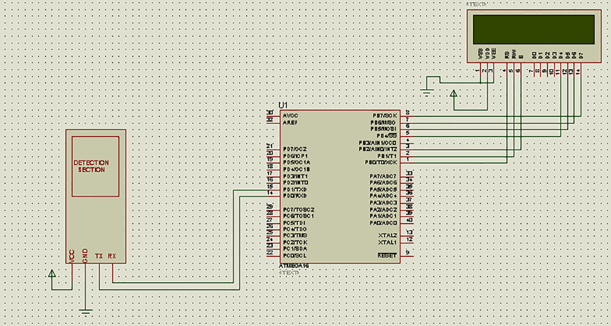
In today’s secure world biometric safety is on the top. Unlike other techniques which make use of passwords and numbers, that are needed to be remembered, biometric techniques make use of human body parts like fingerprints or even iris of your eyes and as we know that these things are unique to all thus it makes biometric systems the most effective over others. In this project I have interfaced a very popular fingerprint scanner R305 with AtMega 16 microcontroller. This module communicates over UART protocol with microcontroller i.e. it makes use of Rx and Tx pin of microcontroller to interact with it.
Now talking about this module, it comes preloaded with scanner as well as detection section and we are left with 4 pins for connections. These 4 pins are: VCC, GND, Rx and Tx. It works over 3.3 to 5V supply and its Rx and Tx pin is connected to Tx and Rx pin of the microcontroller respectively. The mode is semi duplex asynchronism serial communication and the default baud rate is 57600bps but it can be changed between 9600~115200bps.
At power on, it takes about half a second for initialization, during this period the module can’t accept commands. The system sets aside a 512-bytes memory (16 pages X 32 bytes) for user’s notepad, where data requiring power-off protection can be stored. There is an image buffer and two 512-byte-character-file buffers within the RAM space of the module. This buffer serves for image storage and the image format is 256*288 pixels. Two character file buffers can be used to store both character file and template file. System sets aside a certain space within Flash for fingerprint template storage, that’s fingerprint library. It is non volatile in nature. This module also serves the purpose for providing any 32 bit random number.
When communicating, the transferring and receiving of command/data/result are all wrapped in data package format.
ADDER: Default value is 0xFFFFFFFF, which can be modified by command. High byte transferred first and at wrong adder value, module will reject to transfer.HEADER: Fixed value of 0xEF01
PACKAGE IDENTIFIER: Its size is one byte. 01H for command packet and 07H for acknowledge packet.
PACKAGE LENGTH: Refers to the length of package content (command packets and data packets) plus the length of Checksum ( 2 bytes). Unit is byte. Max length is 256 bytes.
PACKAGE CONTENTS: It can be commands, data and command’s parameters, acknowledge result, etc. (fingerprint character value, templates are all deemed as data)
CHECKSUM: The arithmetic sum of package identifier, package length and all packages contends. Overflowing bits are omitted. High byte is transferred first.
Let me clear this concept with an example:-
To change the Modules Address, a command package like this is needed to be sent to it:
If change becomes successful this type of acknowledge package will be received by it:
*If there will be any error while doing this task, this CODE will change to 0x01.
If change becomes successful this type of acknowledge package will be received by it:
Coming back to this project I have made use of only few functions out of several. These are:
- Collecting finger image
- Generating character file from that image
- Generating template for this character file
- Storing template in Flash library
- Deleting template from Flash library
- Searching finger library
When enrolling, user needs to enter the finger two times. The system will process the two time finger images, generate a template of the finger based on processing results and store the template. When matching, user enters the finger through optical sensor and system will generate a template of the finger and compare it with templates of the finger library. For 1:1 matching, system will compare the live finger with specific template designated in the Module; for 1:N matching, or searching, system will search the whole finger library for the matching finger. In both circumstances, system will return the matching result, success or failure.
Here N is the maximum number of templates flash library can store. Mine has 1000.
I would recommend going through its datasheet and understanding how to communicate with it and see what all functions it can perform. I have attached the PDF file of the same in this folder itself.
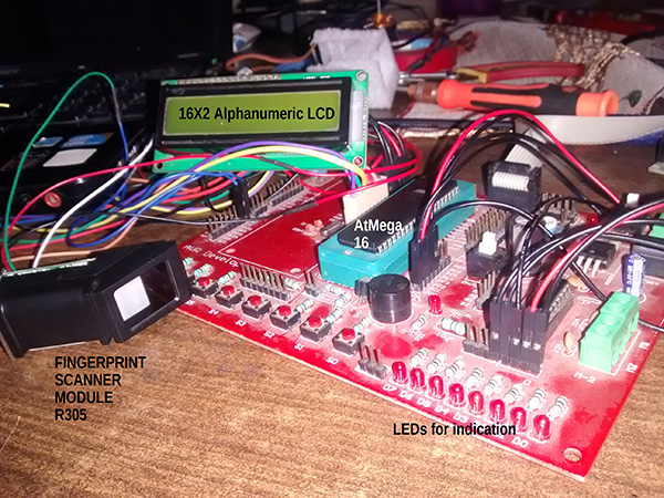
In this project you will see that on powering up the microcontroller the fingerprint module will take certain time to initialize itself, thus I have given it plenty of delay time to do so. Also the status will be shown on a 16X2 LCD and some LEDS as well.
LCD is connected to PORTB and will work under 4 bit mode. LEDs are connected with PORTC.
For more detail: Fingerprint Detection using Microcontroller
-
How does the R305 module communicate with the microcontroller?
The module communicates over the UART protocol using the Rx and Tx pins of the microcontroller. -
What is the default baud rate for the fingerprint module?
The default baud rate is 57600bps, though it can be changed between 9600 and 115200bps. -
How long does the module take to initialize at power on?
It takes about half a second for initialization during which the module cannot accept commands. -
What voltage range does the R305 module work over?
The module works over a 3.3 to 5V supply. -
How many templates can the flash library store?
The maximum number of templates the flash library can store is 1000. -
What happens when a user enrolls their fingerprint?
The user needs to enter their finger two times so the system can process the images and store the template. -
Which ports are used for the LCD and LEDs connections?
The LCD is connected to PORTB working under 4 bit mode, while LEDs are connected to PORTC.
