This tutorial explains how to make your own power supply unit for all your electronics andembedded system experiments. It also has a backup battery which will be used in case of power cuts and a display.
Components Required
1. SLA 12V battery
2. Banana Jack connectors female (2 pairs each)
3. Screw Terminals (1 pair)
4. SPST switch (ratings 5A or more)
5. Adjustable Voltage Regulator LM317 x 2
6. Voltage regulators 7805, 7809, 7812
7. GPCBs
8. Step-down Transformer 16-18V/3 Amps
9. 1N4007 Diodes x 4
10. Two Relay Module
11. Capacitors
12. Resistors
13. ATmega16/8 Development board
14. 16×2 LCD
15. Heat Sinks
16. Enclosure
Features:
– Inputs: 220-240V, 50Hz AC
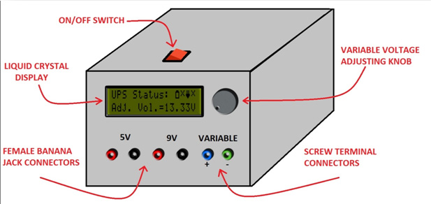
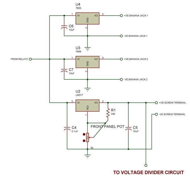
– Outputs: 1 X 5V and 1 X 9V (available through banana jack)
1 X Adjustable voltage (available through screw terminal)
– Adjustable Voltage Range: 1.25-14.5V in Mains Mode and 1.25-10.5V in Battery Mode
– Modes: 1) Battery Mode and 2) Normal Mode (Through Mains)
– Automatic Switching and Shutdown by Microcontroller
– LCD with various indicators.
Blue line indicates signal lines and black lines indicate power lines.
Let me explain you what each block consists of and its function.
Mains Block: This consists of the transformer, bridge rectifier (4 diodes) circuit and a capacitor. This block takes in the power from a wall socket which provides 220-230V AC. The step-down transformer scales down the amplitude of the sine wave, followed by the bridge rectifier which converts it into pulsating DC which when passing through capacitor yields a unregulated DC power of 16-18V (voltage depends on transformer)
Charger Circuit: This block mainly consists of an adjustable voltage regulator LM317 which along with other components works as constant voltage, current limited charger for our battery. Once the battery is full charged, the circuit automatically supplies low current to the battery and goes into trickle charging mode.
For more detail: Un-interruptible Bench-top DC Power Supply With Display
About The Author
Ibrar Ayyub
I am an experienced technical writer holding a Master's degree in computer science from BZU Multan, Pakistan University. With a background spanning various industries, particularly in home automation and engineering, I have honed my skills in crafting clear and concise content. Proficient in leveraging infographics and diagrams, I strive to simplify complex concepts for readers. My strength lies in thorough research and presenting information in a structured and logical format.
Follow Us:LinkedinTwitter