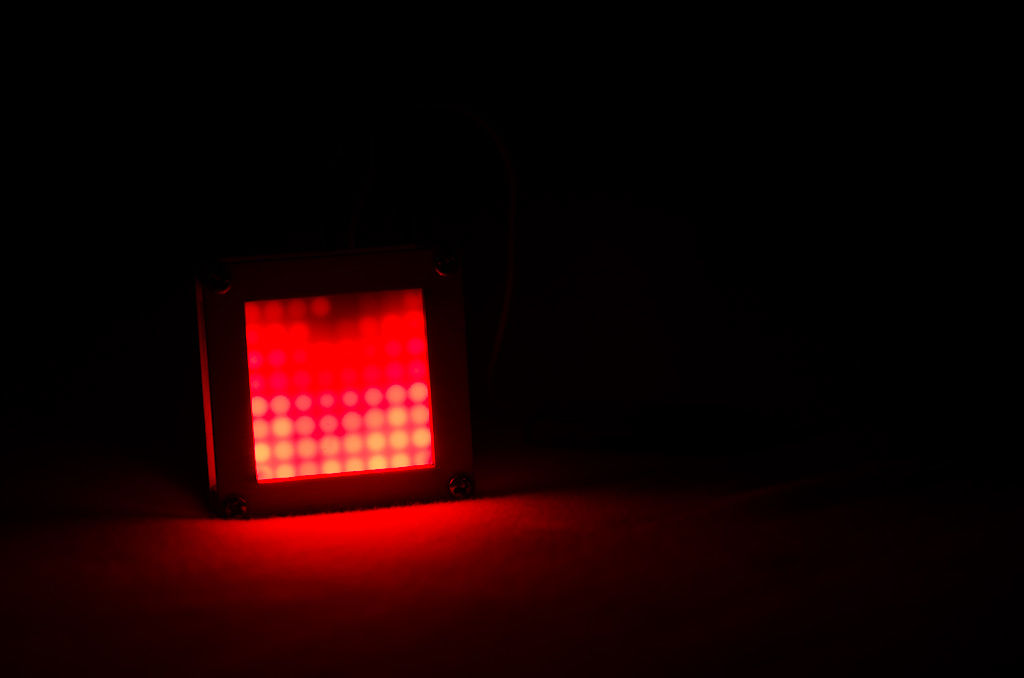
Summary of Flames effect with a 8×8 LED Matrix and ATMega328
This article details the construction of an 8x8 LED matrix pendant powered by an ATMega328 microcontroller. The project involves soldering components onto a board, initially testing on a breadboard, and utilizing specific code optimized for Arduino to display effects like flames. The author notes that while the concept was inspired by previous blog posts, this guide provides missing details on parts selection and assembly techniques.
Parts used in the 8x8 LED Matrix Pendant:
- ATMega328
- 8x8 LED matrix (specifically SZ*21588 or SZ*11588 models)
- Metal pins
- 10k ohm resistor
- 100uF capacitor
- 2 x 22pf Capacitor
- 16 MHz crystal
- AVR programmer
- Soldering iron and assorted accessories
- Power source (2 x CR2032 cell batteries connected in series)
A while ago I found some blog posts explaining how to use a LED matrix as a pendant (http://hackaday.com/2013/01/10/8×8-led-matrix-pendant-sealed-in-a-block-of-epoxy/ and https://sites.google.com/site/tinymatrix/ ). The 8×8 matrix pendant looked cool, but it was missing detailed information on which parts to use and how to solder everything together.
With help from a friend, Uriel Guy, we managed to figure out how to make it work. Well, actually, Uriel did most of the work… including of cleaning up the code, modifying it to work with Arduino, and optimize it. I’m just writing the instructable because he got lazy 🙂
By the way – the code itself is a piece of art. Check it out if you want to see how to implement 16 levels of red using the dot matrix.
Step 1: Materials
You’ll need the following –
- ATMega328
- 8×8 LED matrix. I used the 38mm x 38mm (see the comments below)
- Metal pins
- 10k ohm resistor
- 100uF capacitor
- 2 x 22pf Capacitor
- 16 MHz crystal
- AVR programmer
- Soldering iron and assorted accessories
- Power source. I used 2 x CR2032 cell batteries connected in series
Note about LED Matrix – I used a 38mm x 38mm matrix because it hides the ATMega328 well. The code in this instructable is designed to work with a SZ*21588 matrix, where rows are ground and columns are positive (attach link to schematic and bad schematic). If you are not sure what I am talking about, make sure your schematics look like the one I attached to this instructable. Note that when I ordered mine I ordered two pieces from EBay, and I got two different models – SZ*21588 and SZ*11588. So make sure you know what matrix you ordered. Or just modify the code accordingly.
Step 2: Getting everything ready + testing

You should first place the “Arduino” parts (ATMega, crystal, etc) and try a blink example (sorry, but I won’t cover this part in this Instructable).
After you got the example to work, hook up the matrix and load the code using Arduino IDE (or whatever IDE you are using). Make sure you got Pin #1 of the matrix in the right place (as shown on my lovely sketch).
Is it working? Great. Time to do some soldering.

Step 3: Soldering
A little bit of warning now – this part can get really confusing, so read carefully. We actually got everything soldered the wrong way on the first attempt… and it was a pain to take apart.
For more detail: Flames effect with a 8×8 LED Matrix and ATMega328
- Which LED matrix model is recommended for this project?
The SZ*21588 matrix is designed for the provided code where rows are ground and columns are positive. - What size LED matrix hides the ATMega328 well?
A 38mm x 38mm matrix is used because it effectively conceals the ATMega328 chip. - How should the power source be configured?
The project uses two CR2032 cell batteries connected in series. - What is the first step before soldering everything together?
You must place all parts on a breadboard to test if they work correctly. - Can I use different LED matrix models than the one specified?
Yes, but you must ensure your schematics match or modify the code accordingly if using a different model like SZ*11588. - Why did the author write this instructable?
The author wrote it because their friend Uriel Guy did most of the work including cleaning up the code and optimizing it. - What level of color control does the code support?
The code implements 16 levels of red using the dot matrix.