USB I / O circuit ATMEGA88 based on the usb connection FT232R is done via detailed ir project ( German explanation ) the C source code, circuit diagrams and PCB drawing of the picture… Electronics Projects,FT232R USB I-O Circuit ATMEGA88 “avr project, microcontroller projects, “
USB I / O circuit ATMEGA88 based on the usb connection FT232R is done via detailed ir project ( German explanation ) the C source code, circuit diagrams and PCB drawing of the picture ‘s project uygulanmasa similar circuit for the enlightened can give . TARGET 3001 program prepared by the circuit diagram tarv15viewer_e.ex in the file and run the program open the file schaltplan_layout.t3001
Function overview :
6x digital input
2x analog output
3 PWM output
1x I2C bus connection
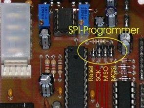
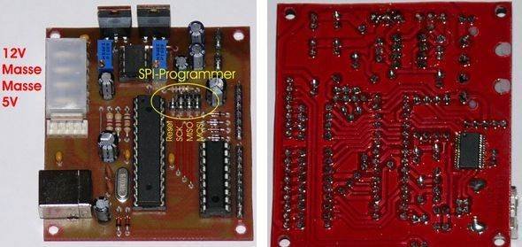
Programming SPI transfer port for renovation
PC connectivity
RS232 = 38400 baud, 8 data
Simple ASCII commands USB -I / O
RS232 ring buffer of 550 bytes in size
With 200 bytes of user ( user0 ) memory (virtual )
54 bytes for the user ( user9 ) memory (EEPROM)
8- bit PWM with 122Hz ( ideal for LED control )
Hardware and software watchdog
Displays all commands sent
I2C -bus search tool, error messages and more
Source: https://320volt.com/en/atmega88-ft232r-usb-io-karti/ alternative link: ft232r-usb-i-o-circuit-atmega88.rar alternative link2