
Summary of GuGaplexed Valentine LED Heart using ATTiny13V Microcontroller
GuGaplexing is a novel LED multiplexing technique that controls twice as many LEDs as Charlieplexing using extra components. This project demonstrates the method with a Valentine's Heart display featuring 40 LEDs driven by an ATTiny13V microcontroller via five pins, plus a sixth pin for a switch to cycle animations. The circuit relies on matched NPN and PNP transistor pairs to decode logic states efficiently.
Parts used in the GuGaplexed Valentine LED Heart:
- AVR ATTiny13V Microcontroller
- 8-pin socket
- 40 red 3-mm LEDs
- NPN BC547 transistors
- PNP BC557 transistors
- Resistors
- Push button switch
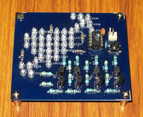 GuGaplexing is a new LED display multiplexing technique. Compared to Charlieplexing, GuGaplexing allows you to control twice as many LEDs, with just a few additional components.
GuGaplexed Valentine LED Heart project has 40 LEDs arranged in an ‘Arrow Piercing a Heart” arrangement using only 5 pins of a microcontroller. The project uses an AVR ATTiny13V Microcontroller. All the 6 I/O pins of Tiny13 are used in this project; 5 for controlling 40 LEDs and the 6th pin to read a switch. Pressing the switch changes the display animation on the pierced heart.
Step 1 The Circuit Diagram
The circuit consists of a Tiny13, 40 red LEDs of 3-mm size, a bunch of BC547 (NPN) and BC557 (PNP) transistors, a few resistors and a push button switch. The Tiny13 is mounted in an 8-pin socket. The schematic in pdf and eagle format are available here.
An important point to note is that the circuit uses 5 transistor pairs using NPN and PNP transistors and these transistors must be matched for their beta values, which is done easily with suitable multimeter with transistor check function.
Briefly, the way GuGaplexing works is as follows: The microcontroller pins operate in one of three possible states: 0, 1 or Z (the high impedence state). Charlieplexing technique makes use of this fact to increase the number of LEDs that can be controlled compared to the conventional multiplexing technique, which does not exploit the third state (i.e. the high impedence state ‘Z’) of the pin. Thus Charlieplexing manages to control N*(N-1) LEDs using N digital pins.
Now wIth 2 pins, there are eight logic combinations: 00, 01, 0Z, 10, 11, 1Z, Z0, Z1 and ZZ. So in principle with suitable decoding of these states, it should be possible to connect 8 LEDs using two pins only, ofcourse at the cost of additional external components for the decoding job. GuGaplexing does a compromise and uses a pair of transistors (NPN and PNP) per pin to decode four of the possible eight combinations. Thats how, for N pins, GuGaplexing achieves 2*N*(N-1), which is twice as many as Charlieplexing.
More details of the GuGaplexing LED display multiplexing technique will be available as a Design Idea on EDN (www.edn.com) in near future.
Step 2 GuGaplexed LED Heart in action
Here is a youtube video of the project in action.
Step 3 Source code
Here is the source code of this project written in C and compiled using winavr gcc. The source code, Makefile and the hex file is attached.
For more Detail: GuGaplexed Valentine LED Heart using ATTiny13V Microcontroller
- How does GuGaplexing compare to Charlieplexing?
GuGaplexing allows you to control twice as many LEDs compared to Charlieplexing. - What microcontroller is used in this project?
The project uses an AVR ATTiny13V Microcontroller. - How many LEDs are arranged in the heart design?
The project has 40 LEDs arranged in an Arrow Piercing a Heart formation. - How many microcontroller pins are utilized for controlling the LEDs?
Five pins are used to control the 40 LEDs while the sixth pin reads the switch. - What happens when the push button switch is pressed?
Pressing the switch changes the display animation on the pierced heart. - Why must the transistors be matched?
The circuit uses five transistor pairs that must be matched for their beta values. - What type of transistors are required for the circuit?
The circuit requires a bunch of BC547 NPN and BC557 PNP transistors. - Can I find the schematic files online?
Yes, the schematic in pdf and eagle format are available on the project page. - Where will more details about GuGaplexing be published?
More details will be available as a Design Idea on EDN in the near future.
