Introduction
Security is important for everyone from our homes to places of work. You need to feel safe when you are sleeping at night. You might have important documents that you need to keep private. Sometimes you have property in your house that must be secured. Well, you need a good security system. This way you can leave the house and travel for your holidays without having to worry about break-ins. Intruders will stay way from your home when you have a perfect alarm security system. This security system is one that you can get the hardware components at your local store. You will be able to design it yourself after I take you step by step on how to do it. I will take you through steps on how to make a security with motion detection.
The instructions will be clear and straight to the point to ease your work. The components are pocket friendly and will not cost you a fortune. Value for your money is considered while you help yourself to a secure place. The PCB assembly will entail a number of tools and materials. We will use the PIR sensor and Arduino to come up with an alarm security system. With a motion sensor you can have the chance of doing something before things take a turn. For instance, when there is an intruder and the alarm goes on, you will alert the authorities. Safety is paramount to you and your family.
Arduino is being used in this project as its a complete board built using AVR microcontroller family. Easy to build project, with hundred of library code samples and much more.
Materials needed
- Speaker
- Arduino Uno
- LED of your choice
- Assorted wire
- PCB board
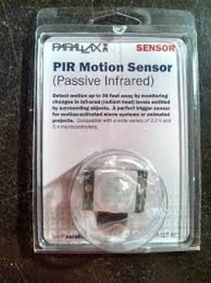
- A parallax PIR motion sensor
- Plastic card box
- Zip ties
- Spray paint
- A Solder
Tools required include;
- A Soldering iron
- A Computer and also Arduino USB cable
- A drill
- A saw
- Wire strippers
Procedure
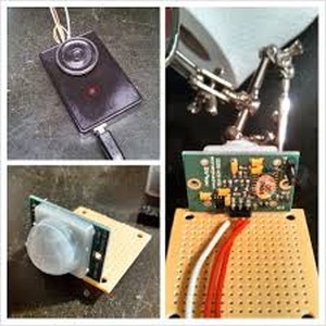
1.Assembling the PIR Sensor
The first step is to assemble the motion sensor. You will need to open the sensor and Printed Circuit Board (PCB). After opening the two materials you can then proceed to position the three pins that are in the sensor on to the Printed Circuit Board. After positioning it on the row at the front, you can now solder it directly to the board. The board that you will solder is the one with the metallic pads, not the blank one
After soldering the parts you will then examine the pins. You should be keen so that you can properly have the pins. They should read as VCC, GND, and OUT. Later you will use the VCC to plug in the +5V. The GND will proceed to the ground and as for the OUT, it will go to the digital pin meant for the Arduino.
Then you have to solder three wires just behind where you had soldered the three pins before. This means that on the board bottom you will have a total of 6 solder points. You have to do this right so that at the end you have the correct alarm security system. You can now connect each pin to the solder points. Depending on the position of the sensor that you need, ensure that the wires are long enough.
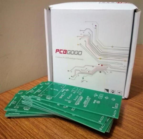
PCB Board
2. Setting up the Arduino
This will be a simple task that will take a short time. It will require you to first connect the GND wire of the PIR sensor that goes to the ground to the Arduino. The next step is to also connect the VCC on the sensor to the Arduino. Finally connect the OUT from the sensor to pin #7 on the Arduino as well. The instructions here are simple and precise to follow.
By now you need to get the LED and the speaker so as to fix it on the Arduino. For the speaker you can go ahead and connect the + to pin #9 of the Arduino. You can then connect – of the speaker to the ground of the Arduino. The LED is the next connection whereby you will fix the long leg to pin #13 of the Arduino. You can also get the short leg of the LED and connect it to the ground of Arduino. The ground is next to pin#13 hence it will not be a challenge to find.
At this time the end result will tell you if you did the PCB SMT well. Upload the sketch to the board that you have and then plug the Arduino in. You will be able to see some light. If you really connected the PIR sensor to the Arduino in the right way, there will be a buzzing sound. It will happen even without movement. These two signs will alert that you did the work well. After approximately fifteen seconds, the sensor will then calibrate and the buzzing sound will automatically go off. You will now have a functional security system at this point. The finished product will be able to sense any movements around your place of residence or your work place.
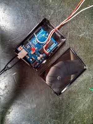
3. Finalising the system
With a plastic card box and paint the end product will be even better. Using the card box cut all the holes so that the wires are let out. You can ensure that everything else is well tucked in. The holes will be one at the back for the wires to the speaker and also the sensor. The second hole at the top will serve the LED. The last hole at the front will be for the USB cable that powers the Arduino.
The spray paint will come in handy now. You can choose the colour you like as per your taste and preference. The enclosure box will then be appealing after you have done an excellent painting. The alarm system will now be ready for use. The alarm will be triggered whenever there is any motion and you can check it out. A feeling of satisfaction will engulf you as you see the work of your hands.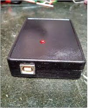
Conclusion
This PCB project is simple and easy to follow. You will not go wrong when you follow the steps keenly. As I had earlier said, the hardware components are available in the market. The best part is that you can customize the end product how you like it. I hope this inspires you to create your own alarm security system. If you are interested, I can sponsor you the PCB board. You can be sure that I will send one to you. We can make arrangements on how best you can purchase the equipment. You can go ahead and reach put to me through my website link.
Thanks for PCB prototype manufacture PCBGOGO to sponsor me this project.
If you like it, please share it and you also can buy some nice PCB form them.