Summary of How to use Push Button with ATMEGA32 AVR Microcontroller
This tutorial explains interfacing a push button with the AVR ATmega32 to control an LED and demonstrates using if-else in C. It covers pull-up and pull-down wiring modes, shows example GCC C code for Atmel Studio (button on PC5, LED on PD4), and walks through Proteus simulation setup including clock, fuse, HEX upload, and running the simulation to observe the LED behavior when the button is pressed.
Parts used in the Push Button with ATMEGA32 AVR Microcontroller Project:
- ATmega32 microcontroller
- Crystal oscillator (16 MHz)
- Capacitors (for crystal and decoupling)
- Resistors (pull-up or pull-down resistor)
- Push button
- LED
- Proteus software (for simulation)
- Atmel Studio 6 (GCC C project environment)
- HEX program file (generated from Atmel Studio)
This tutorial will provide an understanding of push buttons and their integration with the AVR ATmega32 microcontroller. While push buttons can be applied to control various devices, we will focus on using them to manipulate an LED in this demonstration. Additionally, we will delve into the utilization of “if and else” statements in the C programming language.
In the preceding guide, we acquired knowledge on harnessing the GPIO pins of the ATmega32 microcontroller for digital output purposes. In this tutorial, our attention shifts to their application as digital input pins.
What is Push Button?
A push button is a compact control device activated by pressing, typically used to operate electrical equipment. In this article, we demonstrate the use of this button in conjunction with the AVR microcontroller Atmega32 to offer a fundamental understanding of how to create code for device control.
Push Button Interfacing with ATmega32
When we aim to connect a push button to a microcontroller, our primary goal is to determine the button’s state, whether it’s pressed or not. A push button, when pressed or released, yields either a logic high or a logic low output, contingent on the specific configuration of the push button circuit.
Interfacing a push button with an ATmega32 microcontroller can be accomplished using two different configuration modes. Let’s explore each of these modes individually.
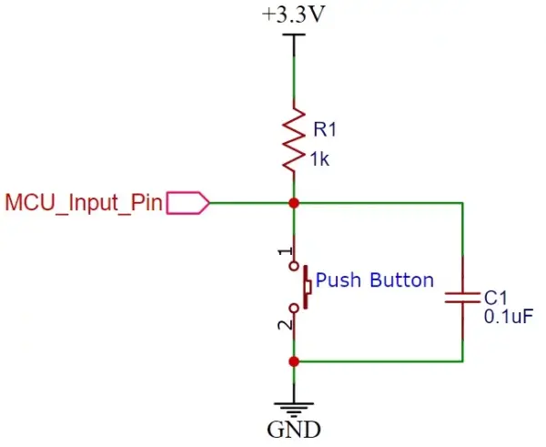
Pull-Up Mode
In Pull-up mode, the MCU_Input_Pin registers a logic high input when a push button is in the unpressed state. This occurs because a 3.3V signal, channeled through an R1 resistor, is present at the input terminal. Conversely, when the push button is pressed, the metallic contacts within the push button establish a connection between the ground terminal and the input terminal. Consequently, a logic low input is detected on the digital input pin of the ATmega32 microcontroller. In summary, by reading the status of the push button using a digital input pin on the microcontroller, we can determine whether the push button is pressed or not. The accompanying schematic diagram illustrates the connection of a push button with a pull-up resistor.
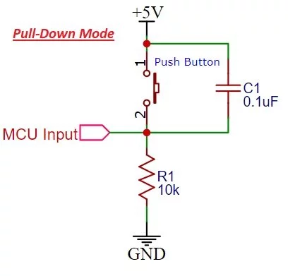
Pull-Down Mode
In the Pull-down mode, an ATmega32 GPIO pin receives a logic low input when a push button is not pressed. This occurs because a ground reference signal is connected to the input terminal via an R1 resistor. Conversely, when the push button is pressed, the metallic contacts of the button establish a connection with the +5V signal and the input terminal. As a result, a logic high input is registered on the ATmega32’s digital input pin. The accompanying schematic diagram illustrates the configuration of a push button in conjunction with a pull-down resistor.
Develop the Code
To begin, we need to create the code within Atmel Studio 6. We’ll be writing the code in the C programming language, utilizing a push button as the control mechanism for an LED. When the button is pressed, the LED will illuminate, and when it’s released, the LED will cease blinking.
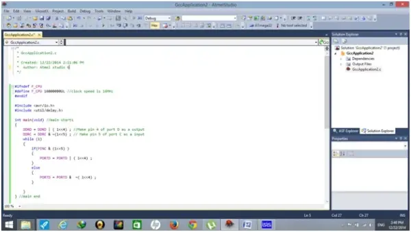
1. Launch Atmel Studio 6 and initiate a new project by selecting “New Project.” Opt for the “GCC C Executable Project” option. Afterward, specify the target device, in this case, the Atmega32, and click “OK.” This action will open a new workspace where you can begin writing your code.
2. To regulate the LED’s blinking behavior via a push button, you can refer to the following code snippet:
ATmega32 Control LED with a Push Button Code
In this code, we make use of two registers: the Data Direction Register (DDR) and the PORT Register. The DDR register specifies the pin’s direction, indicating whether it functions as an input or output. On the other hand, the PORT register serves as an output register, revealing the state of a pin, whether it is set to a high or low state.
A push button is linked to the fifth pin of PORT C, while an LED is attached to the fourth pin of PORT D. When the push button is pressed, the LED will illuminate; otherwise, it will stay in an off state.
#ifndef F_CPU
#define F_CPU 16000000 UL //clock speed is 16MHz
#endif
#include <avr/io.h>
#include <util/delay.h>
int main(void) //main starts
{
DDRD = DDRD | (1 << 4); //Make pin 4 of port D as a output
DDRC = DDRC & ~(1 << 5); // Make pin 5 of port C as a input
while (1) //initialize while loop
{
if (PINC & (1 << 5)) //if PIN5 of port C is high
{
PORTD = PORTD | (1 << 4); //PIN4 of port D is high
} else //otherwise
{
PORTD = PORTD & ~(1 << 4); //PIN4 of port D will remain low
}
} // while loop ends
} //main end
Code Explanation
In this section, we will delve into the functionality of this code.
#ifndef F_CPU
#define F_CPU 16000000 UL //clock speed is 16MHz
#endif
#include <avr/io.h>
#include <util/delay.h>
To start, we configure the ATmega32 microcontroller to operate at a clock speed of 16 MHz. Subsequently, we import the header files <avr/io.h> and <util/delay.h>. These header files manage the input/output pins and provide functionality for controlling time delays in the microcontroller.
int main(void) //main starts
{
DDRD = DDRD | (1 << 4); //Make pin 4 of port D as a output
DDRC = DDRC & ~(1 << 5); // Make pin 5 of port C as a input
Within the main function, we initiate by specifying that port D’s pin 4 is set as an output. Subsequently, we designate port C’s pin 5 as an input.
while (1) //initialize while loop
{
if (PINC & (1 << 5)) //if PIN5 of port C is high
{
PORTD = PORTD | (1 << 4); //PIN4 of port D is high
} else //otherwise
{
PORTD = PORTD & ~(1 << 4); //PIN4 of port D will remain low
}
} // while loop ends
} //main end
Finally, within the while loop, we perform a check to determine if pin 5 is in a high state. This particular pin is linked to the push button, which means that when the button is pressed, it sends a high logic signal to pin 5 of port C. In response, we can set pin 4 of Port D to a high state, illuminating the LED. In the event that the button is released or not pressed, the else condition takes effect, keeping pin 4 of port D at a low state. This concludes the while loop and, subsequently, the main function.
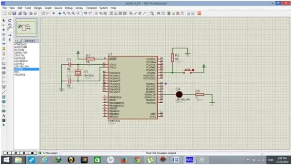
Proteus Schematic and Simulation
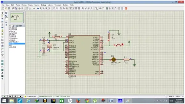
The schematic design in Proteus is displayed below. Within this design, we incorporate components such as the Atmega32 microcontroller, a crystal oscillator, capacitors, resistors, an LED, and a push button, all of which are readily available in the Proteus library. It’s worth noting that the VCC and ground pins of the Atmega32 are automatically connected, eliminating the necessity for manual connection, unless, of course, you are implementing this in a physical setup.
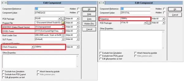
Once you’ve completed the circuit design, make the required adjustments by double-clicking on both the crystal and Atmega32. A dialog box will then be displayed, allowing you to configure the frequency settings for the crystal and Atmega32, which should be set to 16 MHz, as well as the fuse bits for the Atmega32.
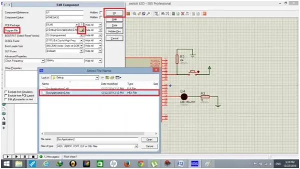
Once more, perform a double-click on Atmega32, which will trigger the appearance of a dialog box. Within this dialog, navigate to the “Program File” option, choose the HEX file you need, and then click the “OK” button.
The last action to take is to click the “play” button located in the lower-left corner of the Proteus window. When you do this, the circuit will demonstrate that when the push button is pressed, the LED will illuminate.
Source: How to use Push Button with ATMEGA32 AVR Microcontroller
- What does the tutorial demonstrate?
Using a push button with ATmega32 to control an LED and using if and else in C. - How is the push button wired in pull-up mode?
Input reads high when unpressed via resistor to VCC; pressing connects the input to ground producing a low. - How is the push button wired in pull-down mode?
Input reads low when unpressed via resistor to ground; pressing connects the input to +5V producing a high. - Which pins are used for the button and LED in the example code?
Push button is on pin 5 of PORTC (PC5) and LED on pin 4 of PORTD (PD4). - How does the code detect a button press?
The code checks if PINC & (1 << 5) is true; if so it sets PORTD bit 4 high to turn on the LED. - What development tools are used to build the project?
Atmel Studio 6 for writing/compiling C code and generating the HEX file, and Proteus for schematic and simulation. - What clock speed is configured for ATmega32 in the example?
The MCU is configured to run at 16 MHz. - How do you load the program into Proteus for simulation?
Double-click the ATmega32 in Proteus, select Program File, choose the HEX file, and click OK. - What happens in the Proteus simulation when the button is pressed?
The LED illuminates when the push button is pressed.