Summary of How to Work With 32K crystal and AVR Microcontroller
This article shows how to attach a 32.768 kHz external crystal to an AVR ATmega8, use Timer/Counter2 in CTC mode with a 1024 prescaler, and toggle OC2 (PORTB pin 3) to blink an LED. It includes a parts list, circuit notes (DDRB bit for OC2, ASSR usage), a C program initializing ASSR/TCNT2/OCR2/TCCR2, and putting the MCU to sleep while the timer hardware toggles the output.
Parts used in the ATmega8 32K Crystal Project:
- ATmega8
- LED
- Resistor
- Push Button switch
- 32768Hz Crystal
- 33pF Ceramic capacitor (2)
- Programmer (extra)
- Bread board (extra)
- 5V Power Supply (extra)
This article teaches you how to add 32K external crystal source to AVR micro controller (Atmega8 ) with circuit diagram & C program.
Introduction
Timing-is one of the basic function, performed by the micro controllers. Every microcontroller has at least one timer/counter module in its architecture. However if the counter is clocked internally a few issues may arise in some cases. Sometimes the clock frequency may not stable, or sometimes the clock frequency may be too high than necessary. Sometimes external clock is required to have the required quality. To solve these problems, some AVR micro controllers comes up with an inbuilt oscillator supporting 32.768KHz crystal. User just need to attach the tank circuit along with the 32K Crystal.
For a demonstration of this, we would try to blink an LED. We will use the output of the timer. Microcontroller used here is ATmega8. The component list is as below:
Component |
Qty |
| ATmega8 |
1 |
| LED |
1 |
| Resistor |
1 |
| Push Button switch |
1 |
| 32768Hz Crystal |
1 |
| 33pF Ceramic capacitor |
2 |
| Extra: Programmer, Bread board, 5V Power Supply | |
Now, we have one Input Capture register, and we can obtain an electrical output in the OC2 Pin (PORTB, Pin 3). And we must keep the following points in mind while programming:
- Human Eye can sense any periodic activity with at least 100mS of period. TCNT2 Pre-scalar can scale down the clock frequency to ATMOST 1024th PART, Pulse Width Modulation (PWM) modes will divide the frequency to 256th part. This can give a period of AT MOST 8 Second (1024*256/32768). In this demonstration, we are pre-scaling the clock to 1024th Part.
- We can use a NON Pulse width Modulation mode like CTC mode to blink the LED too. In this demo, we are using CTC mode.
- The DDRXn bit (Data Direction Register ‘X’, Bit ‘n’) must be ‘1’, to which, the OC2 ( Output Compare of Timer/Counter 2) is connected. In case of ATmega8, it is pin no 17 of the IC. Corresponding Data Direction Register is DDRB, and pin no is 3.
So let us make circuit and Write the program.
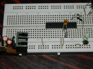
Fig: Circuit Diagram
// Program written for ATmega8

#define F_CPU 1000000

#include

#include

#include
void initTimr()
{ ASSR =0x08; // ASSR enables clocking
// From 32kCrystal
TCNT2 =0x00;
OCR2 =32; // As this is a CTC mode
// value of OCR2 determines
// the period
TCCR2 =0b10011111; // TCCR2 Configured for CTC mode.
// Frequency pre-scaled to
// 1024th Part.
// OCR2 toggles in compare match
while((ASSR&0x07)); // Wait until updating of the
// Above 3 register completes
TIFR =0x00;
}
int main()
{ DDRB=0b00001000; // The DDRXn bit must be ‘1’
// corresponding to OCR2
_delay_ms(2000);
initTimr();
sleep_cpu(); // Halts The CPU. Here, you
// can use ‘while(1);’ too
return 0;
}
Read more: How to Work With 32K crystal and AVR Microcontroller
- What is the purpose of adding a 32.768 kHz crystal to the ATmega8?
To provide a stable low-frequency clock source for Timer/Counter2 so the timer can produce precise low-frequency outputs. - Which pin provides the timer output to blink an LED?
OC2 which is PORTB pin 3 (pin 17 of the IC) provides the timer output. - What timer mode is used in the demonstration to blink the LED?
CTC mode (Clear Timer on Compare match) is used in the demonstration. - What prescaler value is used for Timer2 with the 32K crystal?
The timer is prescaled to 1024th part. - Which register enables clocking from the external 32K crystal?
ASSR (Asynchronous Status Register) is used to enable clocking from the 32K crystal. - What DDRB setting is required for OC2 output?
The DDRB bit corresponding to OC2 (bit 3) must be set to 1. - What OCR2 value is used in the example program?
OCR2 is set to 32 in the example program. - How does the program conserve CPU while the timer toggles OC2?
The program calls sleep_cpu to halt the CPU while the timer hardware toggles the output.