Summary of INFRA RED REMOTE CONTROLLED ROBOCAR USING AVR (ATMEGA32) MCU
This article details the design of an Infrared (IR) remote-controlled RoboCar using an Atmega32 microcontroller. The system enables wireless control of motor movements (forward, backward, left, right) and power switching from a distance of 5 meters. It utilizes a TV remote for transmission, an IR receiver sensor to decode signals via the NEC protocol, and an L293D motor driver to operate DC motors based on C programming logic.
Parts used in the Infrared Remote Controlled RoboCar:
- Atmega32 Microcontroller
- TV Remote Controller
- TSOP1738 or SFH-5110-38 IR Receiver Sensor
- L293D Motor Driver IC
- DC Motors
- IR LED Transmitter
- Timer/Counter Modules
- Power Supply Batteries
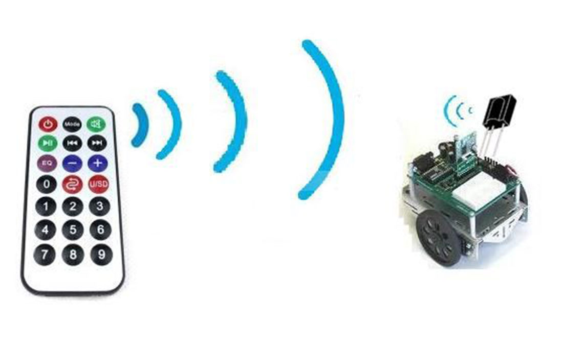
The present PROJECT describes a design and implementation of an infrared (IR) remote controlled RoboCar which can be used for various automated unmanned control applications. I have designed remote controlled RoboCar(left-right/front-back motion). The entire system is based on microcontroller (Atmega32) that makes the control system smarter and easy to modify for other applications. It enables the user to operate or control a RoboCar and operate the mains power switch from about 5 meters away.
Key words: IR Decoder, AVR (Atmega32) Microcontroller, TV remote Controller, Wireless communication
Step 1: IntraRed Communication
IR Communication principle:
a) IR transmission
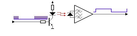
The transmitter of an IR LED inside its circuit, which emits infrared light for every electric pulse given to it. This pulse is generated as a button on the remote is pressed, thus completing the circuit, providing bias to the LED. The LED on being biased emits light of the wavelength of 940nm as a series of pulses, corresponding to the button pressed. However since along with the IR LED many other sources of infrared light such as us human beings, light bulbs, sun, etc, the transmitted information can be interfered. A solution to this problem is by modulation. The transmitted signal is modulated using a carrier frequency of 38 KHz (or any other frequency between 36 to 46 KHz). The IR LED is made to oscillate at this frequency for the time duration of the pulse. The information or the light signals are pulse width modulated and are contained in the 38 KHz frequency. Infrared transmission refers to energy in the region of the electromagnetic radiation spectrum at wavelengths longer than those of visible light, but shorter than those of radio waves. Correspondingly, infrared frequencies are higher than those of microwaves, but lower than those of visible light. Scientists divide the infrared radiation (IR) spectrum into three regions. The wavelengths are specified in microns (symbolized µ, where 1 µ = 10-6 meter) or in nanometers (abbreviated nm, where 1 nm = 10-9 meter = 0.001 5). The near IR band contains energy in the range of wavelengths closest to the visible, from approximately 0.750 to 1.300 5 (750 to 1300 nm). The intermediate IR band (also called the middle IR band) consists of energy in the range 1.300 to 3.000 5 (1300 to 3000 nm). The far IR band extends from 2.000 to 14.000 5 (3000 nm to 1.4000 x 10⁴nm).
b) IR Reception
The receiver consists of a photo detector which develops an output electrical signal as light is incident on it. The output of the detector is filtered using a narrow band filter that discards all the frequencies below or above the carrier frequency (38 KHz in this case). The filtered output is then given to the suitable device like a Microcontroller or a Microprocessor which controls devices like a PC or a Robot. The output from the filters can also be connected to the Oscilloscope to read the pulses.
Applications of IR:
Infrared is used in a variety of wireless communications, monitoring, and control applications. Here are some examples:
· Home-entertainment remote-control boxes
· Wireless (local area networks)
· Links between notebook computers and desktop computers
· Cordless modem
· Intrusion detectors
· Motion detectors
· Fire sensors
· Night-vision systems
· Medical diagnostic equipment
· Missile guidance systems
· Geological monitoring devices
Transmitting IR data from one device to another is sometimes referred to as beaming.
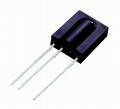
Step 2: IR Sensor & NEC Protocol Fromat
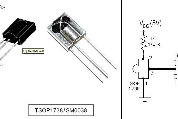
IR sensors(Fig1)
- TSOP1738, SFH-5110-38 (38kHz)
TSOP sensors Features:
- The preamplifier and photo detector both are in single package
- Internal filter for PCM frequency
- Improved shielding against electrical field disturbance
- TTL and CMOS compatibility
- Output active low Low power consumption
- High immunity against ambient light
- Continuous data transmission possible
NEC Protocol:
The NEC IR transmission protocol uses pulse distance encoding of the message bits. Each pulse burst is 562.5µs in length, at a carrier frequency of 38kHz (26.3µs). Logical bits are transmitted as follows (Fig2):
- Logical ‘0’ – a 562.5µs pulse burst followed by a 562.5µs space, with a total transmit time of 1.125ms
- Logical ‘1’ – a 562.5µs pulse burst followed by a 1.6875ms space, with a total transmit time of 2.25ms
The carrier pulse consists of 21 cycles at 38kHz. The pulses usually have a mark/space ratio of 1:4, to reduce the current consumption:
(Fig3)
.
Each code sequence starts with a 9ms pulse, known as the AGC pulse. This is followed by a 4.5ms silence:
(Fig4)
.
The data then consists of 32 bits, a 16-bit address followed by a 16-bit command, shown in the order in which they are transmitted (left to right) :
(Fig5)
.
The four bytes of data bits are each sent least significant bit first. Figure 1 illustrates the format of an NEC IR transmission frame, for an address of 00h(00000000b) and a command of ADh (10101101b).
A total of 67.5ms is required to transmit a message frame. It needs 27ms to transmit the 16 bits of address (address + inverse) and the 16 bits of command (command + inverse).
(Fig6)
.
Time required to transmit the frame:
16 bits for the address (address + inverse) require 27ms to transmit time .and the 16 bits for the command (command + inverse) also require 27ms to transmit time. because (address + address inverse) or (command+command inverse) will always contain 8 ‘0’s and 8 ‘1’s so (8 * 1.125ms) + (8 * 2.25ms) == 27 ms . according to this total time required to transmit the frame is (9ms +4.5ms +27ms+27ms) = 67.5 ms.
REPEAT CODES:
If the key on the remote controller is kept depressed, a repeat code will be issued, typically around 40ms after the pulse burst that signified the end of the message. A repeat code will continue to be sent out at 108ms intervals, until the key is finally released. The repeat code consists of the following, in order:
- a 9ms leading pulse burst
- a 2.25ms space
- a 562.5µs pulse burst to mark the end of the space (and hence end of the transmitted repeat code).
(Fig7)
.
Delay Calculation(1ms):
Clock Freq=11.0592 Mhz
Machine Cycle = 12
Delay=1ms
TimerValue= 65536 – ((Delay * ClockFreq)/Machine Cycle)=65536-((1ms * 11.0592Mhz)/12)
= 65536 – 921= 0xFC67
Step 3: DC Motor Control Using L293D
DC Motor
A DC-motor converts electrical energy into mechanical energy that can be used to do many useful works. It can produce mechanical movement like Go Forward/Backword of my RoboCar. DC motors comes in various ratings like 6V and 12V. It has two wires or pins. We can reverse the direction of rotation by reversing the polarity of input.
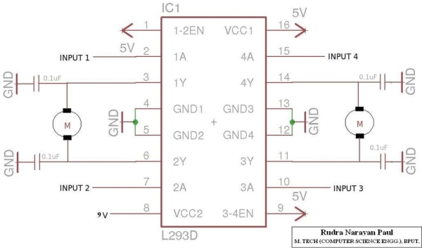
Here we prefer L293D as a rating of 600mA is good for driving small DC motors and protection diodes are included in the IC itself. The description of each pin is as follows:
Enable pins: These are pin no. 1 and pin no. 9. Pin no. 1 is used to enable Half-H driver 1 and 2. ( H bridge on Left side). Pin no. 9 is used to enable H-bridge driver 3 and 4.(H bridge on right side).
The concept is simple, if you want to use a particular H bridge you have to give a high logic to corresponding enable pins along with the power supply to the IC. This pin can also be used to control speed of the motor using PWM technique.VCC1 (Pin 16): Power supply pin. Connect it to 5V supply. VCC2 (Pin 8): Power supply for motor. Apply +ve voltage to it as per motor rating. If you want to drive your motor at 12V, apply 12V on this pin.
It is also possible to drive motor directly on a battery, other than the one used for supplying power to the circuit, Just connect +ve terminal of that battery to VCC2 pin and make GND of both the batteries common. (MAX voltage at this pin is 36V as per its datasheet).GND (Pins 4,5,12,13): Connect them to common GND of circuit.Inputs (Pins 2,7,10,15):
These are input pins through which control signals are given by microcontrollers or other circuits/ICs. For example, if on pin 2 (Input of 1st half H driver) we give Logic 1 ( 5V), we will get a voltage equal to VCC2 on corresponding output pin of 1st half H driver i.e pin no. 3. Similarly for Logic 0 (0V) on Pin 2, 0V on Pin 3 appears.Outputs ( Pin 3,6,11,14): Outputs pins. According to input signal output signal comes.
Motor Movements A B
——————————————————————————————-
……………Stop: Low : Low
……Clockwise: Low : High
Anticlockwise: High : Low
…………….Stop: High : High
Step 4: Circuit Diagrams for Motor Driver and IR Sensor
The ATmega32 is a low-power CMOS 8-bit microcontroller based on the AVR enhanced RISC
architecture. By executing powerful instructions in a single clock cycle, the ATmega32 achieves throughputs approaching 1 MIPS per MHz allowing the system designer to optimize power consumption versus processing speed.
The AVR core combines a rich instruction set with 32 general purpose working registers. All the
32 registers are directly connected to the Arithmetic Logic Unit (ALU), allowing two independent registers to be accessed in one single instruction executed in one clock cycle. The resulting architecture is more code efficient while achieving throughputs up to ten times faster than conventional CISC microcontrollers.
The ATmega32 provides the following features:
- 32 Kbytes of In-System Programmable Flash Program memory with Read-While-Write capabilities,
- 1024 bytes EEPROM, 2K byte SRAM,
- 32 general purpose I/O lines,
- 32 general purpose working registers,
- a JTAG interface for Boundaryscan,
- On-chip Debugging support and programming, three flexible Timer/Counters with compare modes, Internal and External Interrupts, a serial programmable USART, a byte oriented Two-wire Serial Interface, an 8-channel,
- 10-bit ADC with optional differential input stage with programmable gain (TQFP package only),
- a programmable Watchdog Timer with Internal Oscillator,
- an SPI serial port, and
- six software selectable power saving modes.
- The Idle mode stops the CPU while allowing the USART,
- Two-wire interface, A/D Converter,
- SRAM,
- Timer/Counters,
- SPI port, and
- interrupt system to continue functioning.
- The Power-down mode saves the register contents but freezes the Oscillator, disabling all other chip functions until the next External Interrupt or Hardware Reset.
- In Power-save mode, the Asynchronous Timer continues to run, allowing the user to maintain a timer base while the rest of the device is sleeping.
- The ADC Noise Reduction mode stops the CPU and all I/O modules except Asynchronous Timer and ADC, to minimize switching noise during ADC conversions
- In Standby mode, the crystal/resonator Oscillator is running while the rest of the device is sleeping. This allows very fast start-up combined with low-power consumption.
- In Extended Standby mode, both the main Oscillator and the Asynchronous Timer continue to run.
All related circuits are give here and main circuit(atmega32) is also given.
Step 5: Avr Programs
1. For “remote sensor”:
#include
#include
#include “remote.h”
//Globals volatile unsigned int Time; //Main timer, stores time in 10us, //Updated by ISR(TIMER0_COMP) volatile unsigned char BitNo; //Pos of next BIT volatile unsigned char ByteNo; //Pos of current Byte
volatile unsigned char IrData[4]; //The four data Bytes of Ir Packet //2-Byte Address 2-Byte Data volatile unsigned char IrCmdQ[QMAX];//Final Command Received (Buffer)
volatile unsigned char PrevCmd; //Used for repeat
//Variables used for start repeating only after a key is pressed for certain time
volatile unsigned char Repeat; //1=yes 0=no volatile unsigned char RCount; //Repeat count
volatile char QFront=-1,QEnd=-1;
volatile unsigned char State; //State of receiver
volatile unsigned char Edge; //Edge of interrupt [ RISING=1 OR FALLING=0 ]
volatile unsigned int stop;
/**********************************************************************************************/ /* F U N C T I O N S S T A R T S */ /**********************************************************************************************/
void RemoteInit() {
char i; for(i=0;i<4;i++) IrData[i]=0;
stop=0; State=IR_VALIDATE_LEAD_HIGH; Edge=0; Repeat=0;
//Setup Timer1 //———— TCCR0|=((1<
TIMSK|=(1<
OCR0=TIMER_COMP_VAL; //Set Compare Value
unsigned char GetRemoteCmd(char wait) { unsigned char cmd;
if(wait) while(QFront==-1); else if(QFront==-1) return (RC_NONE);
cmd=IrCmdQ[QFront];
if(QFront==QEnd) QFront=QEnd=-1; else { if(QFront==(QMAX-1)) QFront=0; else QFront++; }
return cmd;
}
2. main():
int main(void)
{
uint8_t cmd=0; DDRB=0x08;
DDRD=0x80;
DDRC=0x0f; PORTC=0x00;
while (1) //Infinite Loop to active IR-sensor {
cmd=GetRemoteCmd(1);
switch(cmd) {
case xx: { //BOT Moves forward //Ch+ btn forwardmotor();
break; // Both Motors in Forward Direction
}
………………………………………………….
………………………………………………….
………………………………………………….
default: PORTC=0x00;break; // Both left and right motors halt }
}
}/*End of main*/
……………………………………………………………………………………………………………………
// It a basic model, but I can use it in PWM mode.
Source: INFRA RED REMOTE CONTROLLED ROBOCAR USING AVR (ATMEGA32) MCU
-
How does the IR transmitter work?
The transmitter emits infrared light at a wavelength of 940nm as pulses when a button is pressed, modulated by a carrier frequency of 38 KHz. -
What is the role of the TSOP sensor?
The TSOP sensor acts as a photo detector with an internal filter that discards frequencies other than the carrier frequency to ensure high immunity against ambient light. -
Can I change the direction of the DC motors?
Yes, the direction of rotation can be reversed by changing the polarity of the input voltage to the motor pins. -
What voltage can the L293D drive for the motor?
The VCC2 pin accepts voltage up to 36V according to its datasheet, allowing the use of batteries rated for 6V or 12V. -
How long does it take to transmit one message frame?
A total of 67.5ms is required to transmit a complete message frame including the address and command bits. -
What happens if a key is kept depressed on the remote?
A repeat code is issued typically around 40ms after the message ends and continues at 108ms intervals until the key is released. -
How is the speed of the motor controlled?
The speed can be controlled using the PWM technique by applying a high logic signal to the enable pins of the L293D. -
What is the clock frequency used for delay calculation?
The delay calculation uses a clock frequency of 11.0592 MHz with a machine cycle of 12.