Create your own Interactive LED Beer Pong Table!
This instructable will guide you through all of the steps to in order to create a one-of-a-kind beer pong table complete with cup detecting RGB pods, automatic ball washers, a 32×12 ping pong ball LED grid, side LED rings for spectators and an RF interface to communicate wirelessly with a PC! It will teach you everything from theory of operation to modifying the table to suit your needs. First, I will take you through the modification and wiring of the table before we dive into the software side of things.
The toughest part about this project is just getting it started. There is a lot of prepping and labour to do before you can get anything real exciting working. However, if you can stick it out until you get the 32×12 LED grid in place, you will do just fine. Once you get up to that point, you can really start to see the potential for the table and it makes working on it a lot more enjoyable. I worked on this table on and off over the course of one year. If I were to build another one and had a set schedule of 8-hours per day to work on it, I could easily finish it within one week. The majority of the time that I spent on this project went into prototyping, development and writing the software rather than actually assembling the project.
Now come and take a tour with me through this Instructable and let us find out if you are up for the challenge!
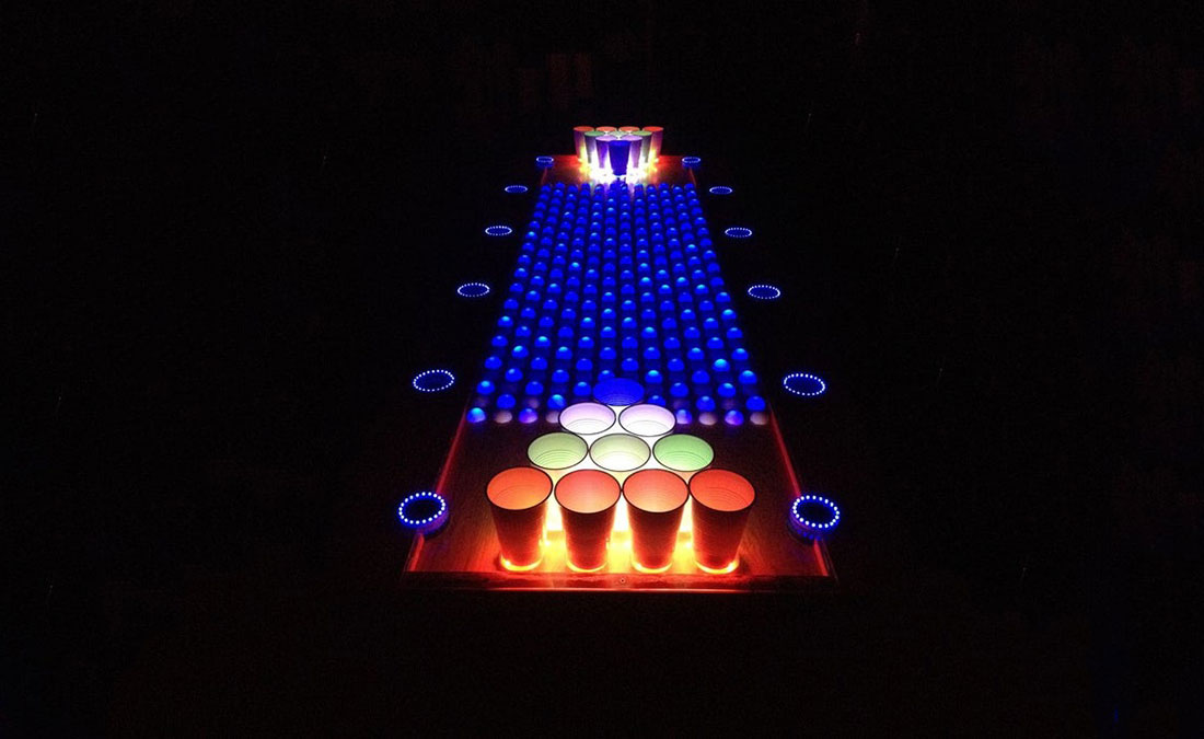
Final Update
I have published a new Instructable that details the operation of the X5 kit and its capabilities. Although I modified the size of the table in the new Instructable, the X5 kit can handle everything that this version can do as well as more. In otherwords, customize your table however you like, whether you build off of this tables layout, the new tables layout or you completely design your own table layout. Thank you to everyone who has been patient with me! There was a lot of time needed to completely re-design the electronics and go through a few revisions before I had a solid product. Cheers!
Step 1: Intro: Gallery
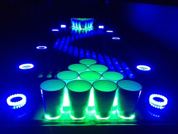
Before we get started we are going to need a little bit of motivation, take a look at these pictures and realize what you will be making. This project is not for the faint of heart, not because it’s difficult, but because it is very tedious and time consuming. Any time that you get frustrated while making this project, take a deep breath, come back to this step, take a look at the pictures and remember what you are working towards!
The pictures and videos that I took don’t even do the table justice either, it really is something else to see up close and personal. The reward outweighs the risk and this one-of-a-kind project is definitely worth building! But we’ve got a long road ahead of us so lets get to it!
Step 2: Theory: What Is Beer Pong?
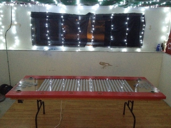
Beer pong is a drinking game in which players throw a ping pong ball across a table and try to hit one of the ten 1/3 filled beer cups on the other side. Once a cup has been hit, the beer is drank from it and it is removed from the table. The first team to clear the opposing teams cups wins the game. Although it is called beer pong, the game can be played with any beverage in the cups such as beer, juice or water. In fact, the World Series of Beer Pong (WSOBP) has switched to only using water in its tournaments so that they abide with all laws and regulations for playing beer pong in bars and public places.
There are many variations to the game so it is a good idea to go over the rules with each team so that each player knows what rules apply before the game begins. If you are unfamiliar with the game of Beer Pong, check out the link below.
Click here to read up on the official tournament rules and typical house party rules.
Step 3: Theory: Project Overview
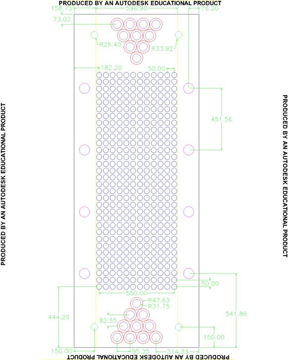
Now before we start building this project we should get a little bit of theory under our belts! The playing surface on this beer pong table is a 2’x8′ Lexan sheet which is considered regulation size. There is 6 inches of extra table on each side of the Lexan sheet which is only used for spectators and their drinks, giving the table a total size of 3’x8′.
The table contains 384 individually controlled LEDs with half of a ping pong ball over top of each LED, 20 RGB Pods that are able to detect whether a cup is over top of the pod and 2 ball washers that will pump a ping pong ball from one side of the table to the other with water, clean it, then blow it back up so that the player can grab it. On each side of the playing surface, we have a 6 inch wooden rail with 4 LED rings per rail and two LED rings for each ball washer.
I have attached a PDF of my AutoCAD drawing seeing as the jpg file isn’t very clear. You will want to print this sheet out and use it for reference when we are modifying the table. I have also attached the AutoCAD 2012 file if you need to modify the table to suit your needs. You may notice that the creation date on that file is August 16, 2011. I actually designed this table and demoed the RGB pods, ball washers and LED grid quite a few years ago. I had just never got around to building the table and integrating all of the features together up until one year ago.
32×12 LED Grid
In the center of the table we can create any animation that will fit into a 32×12 pixel grid. We are able to display scrolling text across it, watch a pong animation, display a sine wave, display the score of the game, etc. There is a huge amount of possibilities! Since we are able to detect when a cup is removed from the table we can make specific animations that trigger exactly when that happens. We’ll get more in-depth with that later.
20x RGB Pods w/ Infrared Sensors
At each end of the table you will see 10 pods. The 16oz cups that are used for beer pong are placed over top of these pods. Each pod contains 4x RGB LEDs and 1x infrared sensor and we are able to light up the pods with any color that we would like. The infrared sensor will detect whether or not a cup is over top of the pod, so if a cup is removed we can change the color of the pod, begin an animation on the LED grid, run an animation on the RGB pods, etc.
Ball Washers
There is a ball washer on each side of the table. The purpose of the ball washers are to…wash the ping pong balls (who would have thought, right!?). The 4x cyan colored holes on the AutoCAD drawing are used to mark the ball washer placement. A player drops a ball into the ball washer hole that is to their left, an infrared sensor will detect the ball and activate the water pump, the water will then push the ball down the pipe while cleaning it, all of the water will be strained out before the end of the pipe and then a fan will turn on and blow the ping pong ball up and out of the ball washer hole to the right of the player. Once the ball is grabbed by the player, the infrared sensor on the right side of the ball washer will detect that the ball is gone and shut off. Each ball washer hole also has a LED ring around it that can be used for animations.
LED Rings
There are a total of 12 LED rings on the beer pong table. The outer railing of the table contains 8 LED rings and the ball washers use the other 4. Much like the 32×12 LED grid, the LED rings are just used for animations. They can be set to go in accordance with music (VU Meter feature must be turned on), fade in and out, flash rapidly or any other cool animation that you can think of. Beer cups can be set inside of the LED rings on the railing which provides a cool effect on the upper lip of the cup.
VU Meter
I have implemented a microphone and an audio amplifier which feeds into the ADC on the microcontroller so that we are able to detect different intensities of sound with the microcontroller. This really adds to the effect of the table and looks really cool as you can turn on different features of the table to different intensities of sound, display a VU Meter on the LED grid and much much more.
RF Module
I have added support for an nRF24L01+ RF module on this beer pong table so that we can control the beer pong table from a laptop. We can send text from the PC to scroll across the LED grid, we can individually select the color of each RGB pod, we are able to set the grid brightness, etc. Seeing as I am still learning the USB protocol, I do not feel comfortable posting my PC software source code yet as it is still really messy and may contain a few bugs. When I get it cleaned up I will be sure to post it! Not a big deal though, I have posted the RF transmitter source code, the PC executable and the source code for the beer pong table in step #82 so that we can still test it out.
The cost to make this beer pong table is around the $400 – $500 mark. The major costs are the 2’x8′ 1/8″ Lexan sheet which was $83, the table itself which was $30 (I got a good deal on a used one) and the 500′ feet of CAT5 (you won’t use all of the CAT5, better to have too much than not enough though) which you should be able to find for $30 – $60. Seeing as I worked on this project over the course of a year, I purchased everything that I needed at different times throughout the year. I never had to fork over $400 at once, just $50 here and $50 there, so it didn’t seem as expensive at the time.
This was just a brief overview of the table. We will go much more in-depth as we get to each feature that is available to us. Take a deep breath, in the next few steps we are going to prepare for construction!
Step 4: Preparation: Skills and Software Required
If you look at this project as a whole it may seem very intimidating. The trick is to break each part down into ‘mini’ projects and integrate them together. You don’t build the whole project, wire everything together and then turn it on hoping that it will all work because chances are that it won’t. Instead, we take baby steps and separate the project into smaller sub-projects, testing the workings of each sub-project before moving on to the next one. By doing it this way you can work out any issues one at a time as you progress.
The following knowledge and skills will help aid you through this project.
- An understanding of digital electronics (multiplexing, data transfer, etc)
- An understanding of C Programming (The whole project is written in C with MPLAB’s C30 Compiler)
- An understanding of binary and hexadecimal numbering systems
- How to solder (This includes SMD components)
- How to crimp ends and create connectors (RJ45, Molex, etc)
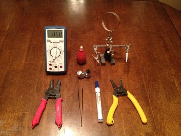
- How to use test instruments such as a multimeter
- How to operate power tools (table saw, drill, jigsaw, etc)
- How to create PCBs or set up circuits on veroboard
If you are not good at soldering SMD components you may want to get somebody who is good at it to help you. The PIC24HJ128GP506A has 64-pins that are 0.22mm wide and only have a 0.28mm space between pins.
Software
All of the software for the beer pong table has been written in C. You will need to download the MPLAB IDE and install it, as well as the C30 compiler to go with it. If you plan on using the RF feature of this table, you will also need the C18 compiler as the RF Master Board uses a PIC18F4550 to control USB and wireless operation.
Step 5: Preparation: Electronic Components
There are 24 PCBs that are required to create this project. Now, 20 of those PCBs are actually single RGB Pods that are placed under the cups (10 on each side). There is then 2 RGB Pod controllers (1x for each side of the table), the 32×12 LED grid controller PCB and the Master PCB which contains the microcontroller. I have created a component list for each category and added up the total amount of components that are needed to assemble the required amount of PCBs in that category.
The majority of these components can be found on eBay but there are a select few which may prove more difficult to find. I have attached a Bill Of Materials to this step which has each component, the required quantity, the price and the vendor where the component(s) can be purchased. The total bill for all of the components (including both power supplies and blue LEDs) listed below comes to $154.66.
Power
1x 12V 5A Power Supply (I used a 12V 10A power supply, only a 5A is needed)
1x 5V 5A Power Supply (I used a 5V 10A power supply, only a 5A is needed)
1x 120V Power Bar
2x 24″ 120V Power Cords
32×12 LED Grid Controller (1x PCB)
- 2x HT1632C LED Drivers
- 1x 2.1mm Power Jack
- 2x Quad RJ45 PCB Mounted Jacks
- 3x Single RJ45 PCB Mounted Jacks
- 16x Quad 150Ω 0603 SMD Resistor Networks
- 500x 5mm Blue LEDs (these are not on the PCB, they are mounted on the table)
RGB Pods (20x PCBs)
- 80x RGB PLCC-6 SMD LEDs
- 60x MMBT2907A SOT23 PNP Transistors
- 60x Quad 150Ω 0603 SMD Resistor Networks
- 20x TCRT5000 Reflective Optical Sensors
- 20x 270Ω 0805 SMD Resistors
- 20x 39kΩ 0805 SMD Resistors
- 20x 8-Pin 0.1″ Polarized Male Connectors
- 20x 8-Pin 0.1″ Polarized Female Connectors
- 160x Crimp Pins for Connectors
RGB Pod Controller (2x PCBs)
- 4x TLC5940 16-Bit PWM Drivers
- 4x 74HC4051 8-Channel Input Multiplexers
- 4x 9-pin 0.1″ Headers
- 4x Quad RJ45 PCB Mounted Jacks
- 4x Dual RJ45 PCB Mounted Jacks
- 2x Single RJ45 PCB Mounted Jacks
- 2x 2-Pin 0.1″ Headers
- 4x 470Ω 0805 SMD Resistors
- 4x 2.4kΩ 0805 SMD Resistors
- 4x 39kΩ 0805 SMD Resistors
- 2x 0.1µF Ceramic Capacitors
- 2x 0.01µF Ceramic Capacitors
- 2x 10µF Electrolytic Capacitors
- 2x 220µF Electrolytic Capacitors
Master Controller (1x PCB)
- 1x PIC24HJ128GP506A-TQFP 10mmx10mm 16-Bit Microcontroller
- 1x TLC5940 16-Bit PWM Driver
- 1x LM386 PDIP Audio Amplifier
- 2x ULN2803ADWR 8-Channel Darlington Array Driver
- 2x MMBT2222A SOT23 NPN Transistors
- 2x 74HC540 8-Bit Inverting Line Drivers
- 1x 74LVC2G125DCUR Line Driver
- 1x LM2576-3.3 Switching Regulator 3.3V 3A
- 1x Quad RJ45 PCB Mounted Jack
- 1x Single RJ45 PCB Mounted Jack
- 2x 1000µF Electrolytic Capacitors
- 1x 220µF Electrolytic Capacitor
- 2x 10µF Electrolytic Capacitors
- 1x 1.0µF Electrolytic Capacitor
- 1x 0.1µF SMD 0805 Capacitor
- 4x 0.01µF SMD 0805 Capacitors
- 2x 27pf SMD 0805 Capacitors
- 3x 1N4148 Diodes
- 1x 1N5822 Schottky Diode
- 1x 100µH Power Inductor (12mmx12mm)
- 4x 10kΩ 0805 SMD Resistors
- 3x 18kΩ 0805 SMD Resistors
- 1x 2.4kΩ 0805 SMD Resistor
- 1x 47kΩ 0805 SMD Resistor
- 1x 100kΩ Trimmer Potentiometer
- 1x 10kΩ Trimmer Potentiometer
- 1x 2kΩ Trimmer Potentiometer
- 1x 20MHz Crystal
- 1x 2.1mm Power Jack
- 16x 2-Pin 0.1″ Male Polarized Connectors
- 3x 2-Pin 0.1″ Male Headers
- 2x 3-Pin 0.1″ Male Polarized Connectors
- 1x Electret Microphone
- 2x 9-Pin 10kΩ 0.1″ SIP Resistor Networks
- 1x SPDT PCB Mounted Switch
- 1x 8-Pin Dual Row Connector
- 2x 5-Pin 0.1″ Male Headers
The passive components and connectors I usually purchase from DIPMicro or eBay. Many of the components/connectors can be changed according to what the user likes, the footprints might just not match the PCB layout. If you are breadboarding or point to point soldering everything together then this wouldn’t be a problem.
Source: Interactive LED Beer Pong Table
