Summary of Introduction to the Atmel ATmega16 Microcontroller
This article introduces the ATmega16 microcontroller and the STK500 development board for mechatronics projects. It details hardware handling, specifically ESD precautions, and outlines the setup of WinAVR software and AVR Studio. The text provides a step-by-step procedure for creating a project, configuring compiler settings, downloading code via ISP, and establishing serial communication using HyperTerminal to print messages.
Parts used in the ATmega16 Microcontroller Project:
- ATmega16 Microcontroller (40-pin DIP)
- STK500 Development Board
- 6-pin ISP ribbon cable
- RS-232 serial cables
- Two-wire jumper
- 10-pin ribbon cable jumpers
- Electrostatic Discharge (ESD) wrist strap
- Grounded ESD mat
- Personal Computer with WinAVR and AVR Studio
Introduction
A microcontroller typically serves as the central “intelligence” of a mechatronic system, functioning as a miniature self-contained computer. It can be programmed to interact with both the system’s hardware components and the user. Even the most basic microcontroller can execute elementary mathematical operations, manage digital outputs, and monitor digital inputs. With the continuous evolution of the computer industry, microcontroller technology has advanced significantly. Modern microcontrollers are considerably faster, possess greater memory capacity, and offer a wide range of input and output functionalities that surpass the capabilities of their predecessors. These enhancements include analog-to-digital converters, high-speed timers and counters, interrupt handling capabilities, outputs suitable for pulse-width modulation, and serial communication ports, among others.
The microcontroller and development board used in this laboratory were generously provided by Atmel for your use. In industrial settings, you can anticipate costs ranging from $50 to $400 for a development board alone, and up to $1000 for a professional compiler and programming interface. Therefore, it is imperative to handle the microcontrollers and development boards with great care and respect. Similar to any electronic device, they are delicate and susceptible to damage. Particular caution should be exercised regarding static charges. Prior to touching the STK500 board or any other circuit board containing integrated circuits, it is vital to ensure the dissipation of any accumulated static charge on your body. The most effective method to achieve this is by using an Electrostatic Discharge (ESD) wrist strap connected to a grounded earth source and placing the circuit board on a grounded ESD mat. If ESD supplies are unavailable, it is advisable to touch a well-grounded metal surface before handling the circuit board.
In summary, the essential guidelines are to employ common sense and adhere to the instructions provided in the laboratory assignments. Each laboratory experience contributes to your knowledge, and you are encouraged to extract as much learning as possible from every experiment and its corresponding examples.
The ATmega16 Microcontroller
The ATmega16 microcontroller utilized in this laboratory is enclosed in a 40-pin wide Dual In-Line Package (DIP) chip. This particular chip was chosen for its durability, and the DIP packaging allows seamless integration with prototyping equipment such as solderless breadboards and solder-type perfboards. It’s worth noting that the same microcontroller is also available in a surface mount package, approximately the size of a dime. Surface mount devices are better suited for circuit boards intended for large-scale production. The diagram presented in Figure 1 below provides a “pin-out” illustration of the ATmega16. This diagram proves highly beneficial as it delineates the connections for power and ground, and establishes the correspondence between pins and their respective functional hardware components, among other details.
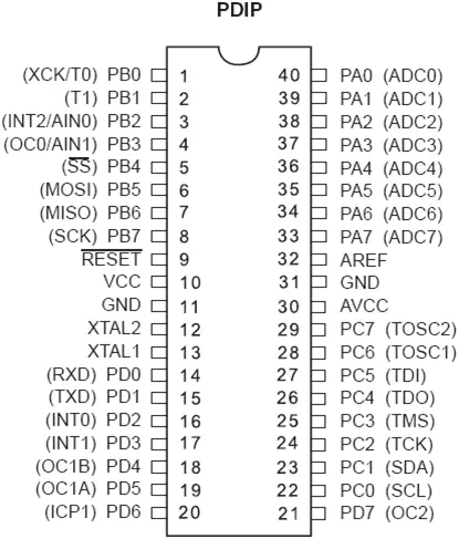
Throughout the semester, it will be essential to acquire knowledge about the ATmega16 (or other components) beyond what is covered in the laboratory instructions. Therefore, it is crucial to acquaint yourself with available documentation from diverse sources. Your initial assignment is to locate the ATmega16 manual and store it for future reference. You can access it in PDF format on Atmel’s website (www.atmel.com), AVRFreaks (http://www.avrfreaks.net/), or by conducting an internet search. This manual provides valuable insights into the features of the ATmega16 and how to utilize them effectively. For instance, you can discover the number of channels for 10-bit A/D converters and the volume of in-system reprogrammable flash memory within the manual.
STK 500 Interface Board
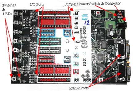
The hardware at your disposal includes the STK500 development board, which is compatible with various microcontrollers within the AVR family (refer to the STK500 user guide for the full list). This board offers users the flexibility to work with multiple Atmel microcontrollers and provides easy access to their input/output (I/O) pins. The STK500 features two serial port connectors: one for programming the devices and another as an extra RS232 port. Additionally, it incorporates a power supply switch and connector, eight LEDs, eight switches for general purposes, and an array of jumpers for board configuration. Figure 2 displays a top view of the STK500 interface board, indicating the placement of key hardware components that you will utilize.
Before proceeding with the process, ensure that you verify the default jumper configurations on the STK500, as depicted in Figure 3.
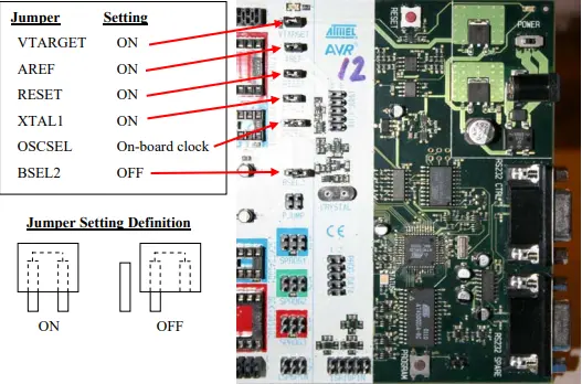
A jumper comprises two female sockets enclosed in a plastic housing, interconnected internally by a metal conductor. Typically, when the pins are joined, the jumper is in the ON position. To place the jumper in the OFF position, you should position it over only one of the two pins. This ensures that the jumper is not misplaced and remains available in case you need to change its configuration. In the case of the OSCSEL jumper, it should connect the two right-most pins of the three, as it is currently set to select the on-board clock signal.
For communication and program download to the microcontroller, you will be utilizing the ISP programming mode. To facilitate this, you should connect the 6-pin ISP ribbon cable from the ISP6PIN header on the STK500 to the 6-pin SPROG3 header highlighted in red just above it, as depicted in Figure 4. It is crucial to align the red stripe on the ribbon cable, indicating pin 1, with pin 1 on each header. Once this connection is established, the STK500 interface board will be prepared for use in your laboratory tasks.
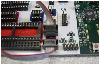
Establish a connection between the ISP6PIN header set on the STK500 and the SPROG3 header set, which is indicated with a red outline, using the provided 6-pin ISP ribbon cable. Ensure that the cable’s red stripe is aligned to connect with pin 1 on both header sets.
WinAVR
There are multiple methods to write, compile, and transfer a program to the ATmega16 microcontroller. Various text editors, compilers, and utilities cater to different programming languages like C, BASIC, and assembly language. Some of these tools are available for free, while others may require a licensing fee for their use. For this course, we will utilize a set of freeware software tools known as WinAVR (pronounced “whenever”). While WinAVR is already installed on the computers in the Mechatronics Laboratory, it is strongly recommended that you download and install it on your personal computer. This way, you can work with your microcontroller outside the lab. Detailed instructions for WinAVR installation can be found in Appendix A at the document’s conclusion.
WinAVR comprises a collection of executable open-source software development tools tailored for Atmel AVR series RISC microprocessors, designed to operate within the Windows environment. It includes the GNU GCC compiler for C and C++, often referred to as avr-gcc.
In the past, programming the microcontroller in embedded systems typically involved direct use of assembly language. Assembly language relies solely on the fundamental instruction set specific to a particular microcontroller. While it can yield fast and efficient code, it has its limitations, as each processor type possesses its own distinct instruction set. Therefore, learning assembly language is not practical unless you are working on a project exclusively dedicated to a particular microcontroller, or if precise timing and memory utilization are critical. In contrast, the C language is widely used in the industry and can be applied across a wide range of platforms. By mastering this language, you can program nearly any microcontroller, provided you have a compiler capable of translating C code into assembly language for your specific controller. The Gnu-C compiler is an open-source freeware C compiler, forming the foundation for compilers that generate code for various microcontrollers and diverse operating systems, including Windows and UNIX.
AVRFREAKS Are Everywhere!
AvrFreaks.com (http://www.avrfreaks.net/) is a dedicated website focused exclusively on Atmel’s AVR processors. It provides access to download links for the latest software versions, up-to-date information on both new and legacy Atmel processors, including user manuals and technical white papers. The site also offers message boards where individuals, just like yourself, can seek answers to their questions and offers general information on compilers, programming interfaces, and more. This website can be an invaluable resource for project development and troubleshooting when working with the ATmega16 microcontroller. Most of the content is accessible to all, but to access certain message boards and downloadable items, user registration is required. The good news is that registration is free. Head over to AvrFreaks.net and create a username for yourself. Be sure to note your AVRFreaks username and include it in your lab report. Before posting any questions on AVRfreaks forums (or any other web forum), we highly recommend reading Eric Raymond’s well-known web post titled “How to Ask Questions the Smart Way,” which can be found at: http://catb.org/esr/faqs/smart-questions.html.
Procedure
Now, it’s time to initiate your initial project. In this first project, you’ll be utilizing a pre-existing example program that illustrates how to print messages via the serial port. It’s crucial to remember these steps as they will be recurring in subsequent labs. The more familiar you become with these procedures, the smoother your future lab sessions will progress.
To facilitate this process, you’ll be employing a no-cost software tool from Atmel called AVR Studio, designed to manage all the necessary files for compiling programs destined for the microcontroller. The following steps will guide you through establishing a structured file system that encompasses the requisite files. (Please note that the computers in the Mechatronics lab already come equipped with AVR Studio and WinAVR. If you plan to work with a microcontroller outside the lab, you will need to independently install this software on your computer. For installation instructions, please refer to Appendix A at the end of this document.)
1. Launch AVR Studio by double-clicking its desktop icon or selecting it from the Start Menu.
2. Access the New Project option by either selecting “Project” from the dropdown menus and then “New Project” or by choosing “New Project” from a popup window that may appear upon launching AVR Studio. This action should bring up the new project window, as displayed in Figure 5.
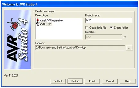
3. Within the new project pop-up window:
– Opt for AVR GCC and input a descriptive name into the Project name field (e.g., FirstAVRproject).
– As you’ll be utilizing provided source code, uncheck the “Create initial file” box.
– Ensure the “Create folder” box is checked.
– Verify that the Location (where your project files will be stored) already exists, allowing you to keep track of your file location. It’s advisable to eventually copy your project files onto a USB drive or email your source files to yourself since files left on the lab computers may be subject to modification or deletion.
– Click the “Next >>” button.
– In the Debug platform field, select AVR Simulator.
– In the Device field, select ATmega16 (not ATmega16A). (Scroll down, as it’s available there.)
– Click the “Finish” button.
4. Configure your project settings by accessing the “Project -> Configuration Options” from the drop-down menu, as depicted in Figure 6.
– Adjust the Frequency to 8000000 (8 million without commas). Note that failing to carry out this step may result in an error regarding F_CPU being undefined.
– Set the Optimization to -O2.
– Click on the “Include Directories” button situated on the left side.
– Click on the New Folder icon (located in the upper right corner) and employ the browse ellipse “…” to add your project folder, created in Step #3 (it appears as .\).
– Click OK.
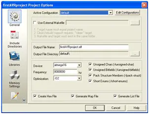
Whenever you create a project in AVR Studio, it’s essential to configure the Frequency and Optimization settings as demonstrated in the left image above. Additionally, you must specify the directory containing your source code (represented as .\) by accessing the Include Directories option, adding it as a new folder, and locating it on your computer, as illustrated in the right image above. If you incorporate code from a different project directory or library, you should also include the locations of their respective directories. In the provided example, AVRlib was included. However, it’s worth noting that AVRlib is not necessary for this laboratory.
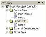
5. Next, proceed to the class website and download the code for this lab. Save the downloaded files into the project folder you created in Step 3. The required files include:
The purpose of this code is to provide guidance on transmitting text strings from the microcontroller to an external device, specifically a PC. The communication protocol employed here is RS-232 serial. For additional details regarding RS-232, please refer to:
Utilizing RS-232 communication allows us to transmit binary data between two endpoints, and this functionality will prove valuable throughout the semester for tasks such as program debugging and interfacing with external components, including sensors and other microcontrollers.
Now, navigate to the Project Directory window positioned on the left side of the screen, as illustrated in Figure 7. Right-click on the Source Files folder icon and opt for ‘Add Existing Source File(s)’. In the ensuing dialog box, choose both uart.c and main_intro.c (by clicking on one file name, holding the CTRL key, and selecting the other), then proceed by clicking OK. Similarly, include uart.h in the Header Files folder by following a comparable procedure, this time commencing with a right-click on the Header Files folder icon.
6. Now, you’re prepared to compile your initial project. To do this, select “Build” from the main menu, followed by “Build” (you can also use F7 or the Build button on the toolbar in future instances). The “Build” action compiles your program. If any errors surface, address them before proceeding. Compiler messages will be displayed in the bottom (Build) window of AVR Studio. Should you encounter an error, you can double-click on the corresponding line in this window, which will navigate you to the problematic line in your program. If needed, don’t hesitate to consult a TA for assistance. Always ensure that the Build log window confirms the absence of errors before proceeding further.
In cases where you had errors and subsequently rectified them, it’s advisable to run the ‘Clean’ routine, which clears any files generated from prior attempts to build your project. When necessary, opt for “Build Æ Clean” from the Tools drop-down menu (or use F7 or the toolbar button in the future) to initiate the Clean process.
7. You are now on the brink of downloading your program onto the ATmega16 microcontroller. Connect the serial cable from COM1 on your computer to the RS232 CTRL connector on the STK500 board (the connector closest to the power jack). Power up the STK500 and switch on the board using the power switch located in the upper right-hand corner. If the board is functioning correctly, you should observe green lights above VTARGET and STATUS.
8. In AVR Studio, select the AVR Program button, as demonstrated in Figure 8 (alternatively, use Tools –> Program AVR). A message at the bottom of this window should confirm that you are connected to your processor. If the message indicates a failure in detecting your controller, double-check your power and serial cable connections, and attempt the process once more. If difficulties persist, seek assistance from your lab instructor.
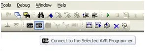
By clicking the ‘Connect’ button, you will launch the STK500 Programming Dialog Box. If you encounter a dialog box presenting you with a list of available programming hardware, please ensure that your STK500 is both connected and powered on. Afterward, select “STK500” and “Auto.”
Now, navigate to the Fuse tab and verify that the fuses are correctly configured, in alignment with the specifications detailed in Table 1 and as illustrated in Figure 9. Fuses encompass individual bits within the ATmega16 EEPROM that govern various parameters, such as clock source, oscillator options, brown-out detection, among others. For more in-depth insights into fuse bits, please consult the relevant sections in the ATmega16 manual. It’s essential to note that fuse bits only require programming once.
Table 1 provides an overview of the Fuse Settings for the ATmega16. It is imperative to confirm that these settings are appropriately configured to ensure the proper functioning of your ATmega16. It is worth mentioning that since we are not employing a bootloader, the choice of Boot Flash section size is unlikely to significantly impact any programs developed in ME 106. Opting for the smallest value will allocate more space for your program code.
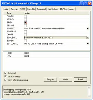
These fuse settings only require configuration the first time a new chip is utilized.
9. Now, proceed to the HW Settings tab and confirm that the STK500 clock generator frequency is configured to 3.686 MHz. Additionally, ensure that the ISP frequency is set to a value that is LESS THAN 1/4 of the ATmega16’s clock speed. (Considering the ATmega’s internal clock is established at 8 MHz, an ISP frequency of 1.843 MHz should be suitable.) The right-hand side of Figure 10 illustrates the HW Settings tab, while the left-hand side depicts the Main tab where the ISP frequency can be selected. If you’ve made any alterations to the fuse settings or ISP frequency, press the ‘Program’ button to write the fuses onto the ATmega16.
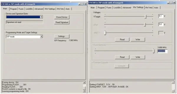
– ISP (In System Programming) serves as the communication protocol employed by the STK500 to program the ATMega16 microcontroller. In cases where the ISP frequency is set excessively high, it can lead to communication errors. Conversely, if the ISP frequency is set too low, it will significantly prolong the time needed to download your program onto the microcontroller.
– If you’ve ensured that both your RS-232 cable and 6-pin jumpers are correctly installed, and you encounter a dialog box titled “ISP Mode Error” with a message like “A problem occurred,” it’s crucial to verify the following:
– Ensure the STK500 is powered on.
– Confirm the serial cable is connected to the “RS-232” (not “SPARE”) labeled 9-pin connector.
– Ensure the 6-pin ribbon cable is correctly linked between the ISP6PIN and SPROG3 headers.
– Make sure that Hyperterminal is not connected to the COM port shared with AVR Studio for programming.
If the issue persists, consult Appendix B for an alternative solution.
– You are now prepared to download your program onto the chip. Refer to Figure 11 below. Access the Program tab. Under the Flash section, utilize the browse button (“…”) adjacent to the ‘Input HEX file’ dialog box to select the hex file corresponding to your program. Locate this file within the folder you created, and open the default folder. The hex file will have a .hex extension and contains the compiled program translated into byte code, which is interpretable by the microcontroller. Click on the Program button within the Flash section to transfer the hex file to the microcontroller. The progress bar will update for a brief moment, and you should observe a series of ‘OK’ messages. If any of these messages are not ‘OK,’ it may be necessary to seek assistance from your lab instructor.
– With your program downloaded, it should now be in operation. To verify this, you’ll utilize HyperTerminal to capture the program’s output on the PC monitor. Turn off the STK500 using the power switch, disconnect your serial cable from the RS232 CTRL connector, and reconnect it to the RS232 SPARE connector on the STK500 board. Additionally, connect the transmit and receive pins from the ATmega16’s UART0 port to the RS232 SPARE connector’s transmit and receive pins. Utilize the two-wire jumper from your lab kit to link the PD0 and PD1 pins of the PORTD header to the RXD and TXD pins respectively on the RS232 SPARE header of the STK500 board. Reference Figure 12 for this connection. It’s important to note that without this connection, you won’t be able to view the output on the serial port. Make sure the red stripe on the 10-pin ribbon cable jumpers is correctly connected to pin 1 at each header on both ends of the jumper, whether connecting the 10-pin SWITCHES header to the 10-pin PORTA HEADER or linking the LED header to the PORTB header. Refer to Figure 12 for the correct configuration.
It’s crucial to note that when you create a new project, the Input Hex File doesn’t automatically update to align with your new project settings. Therefore, it’s vital to ensure that the intended HEX file is selected each time you create or open a new project.
Now proceed to launch a serial communications application such as HyperTerminal (typically found under Start → All Programs → Accessories → Communications). If prompted to provide a name for a New Connection, feel free to enter any name you prefer, and then press OK. Opt for COM1 as the “Connect Using” option and confirm with OK. Configure COM1 properties as follows: 9600, 8, N, 1, N, and then confirm with OK. Power on the microcontroller and press the reset button on the STK500. Take note of what appears on your screen. Does this align with your expectations?
12. You might notice that the floating-point number isn’t displayed correctly. To address this issue, review the comments provided in the uart.h program header file to determine the necessary corrections.
13. Due to your modifications in compiler options, it’s essential to perform a “Build → Clean” operation before proceeding to rebuild your project. Afterward, rebuild your project using “Build → Build” and repeat the steps for downloading and running your program as previously instructed.
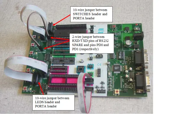
Use a two-wire jumper to establish a connection between the RXD and TXD pins of the RS232 SPARE header, linking them to pins PD0 and PD1, respectively. Additionally, employ two 10-pin ribbon cable jumpers for two specific connections: one to bridge the 10-pin SWITCHES header with the 10-pin PORTA HEADER and another to link the LED header with the PORTB header. While setting up these connections, ensure that the red stripe aligns with pin 1 at both ends of the jumper for each header.
Acknowledgment
We express our gratitude for the generous assistance from the Atmel Corporation, who have provided AVR Starter Kits, STK500 boards, and AVR devices for the benefit of the students and faculty at San José State University.
Appendix A – Installing WinAVR and AVR Studio
The steps below provide a guide for installing WinAVR and AVR Studio. For further assistance with the installation on your specific operating system, you can consult www.avrfreaks.net. Please note that while default directories are typically used, you do have the option to change them as desired. However, it’s essential to ensure that any modifications made are corrected as needed when working on projects, among other tasks.
Installation of WinAVR
1. Commence by downloading the most recent version of WinAVR from the following link: http://sourceforge.net/projects/winavr.
2. Execute the installation of WinAVR by double-clicking on the self-extracting installation program, named WinAVR-version-install.exe, with “version” representing the current version number.
3. During the installation process, you can opt to accept the default settings, unless you have specific reasons to make alterations.
4. Upon completing the installation, the README file will automatically open in your web browser.
Installing AVR Studio
Here’s the rephrased version:
1. To get started, download the latest version of AVR Studio, which requires free registration, along with the latest Service Pack (if available) from this link: http://www.atmel.com/dyn/products/tools_card.asp?tool_id=2725.
2. Run the installation file by double-clicking on it.
3. During the installation process, it is recommended to retain all the default settings and program locations. If, at any point during the installation, AVR Studio prompts you to install the Jungo USB Driver, make sure to check the option for installation. This step is necessary if you plan to use USB-based AVR programmers like the AVRISP mkII and the AVR Dragon.
Congratulations! You are now prepared to initiate ATmega16 programming using WinAVR and AVR Studio.
Appendix B – Handling ISP Mode Error
When attempting to program a new ATmega16 microcontroller, you might encounter a dialogue box labeled “ISP Mode Error” containing a message like “A problem occurred,” as illustrated in Figure B1. This same dialogue box could appear if you forgot to connect either the RS232 cable or the 6-pin ribbon cable required for ISP programming.
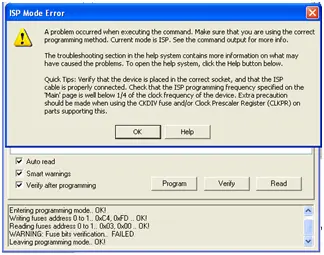
You might encounter this error when attempting to program a brand-new Atmega microcontroller or if there are issues with the RS232 cable or ISP programming cable connections.
If you come across this error, first, ensure that both the RS232 cable and the ISP programming cable are correctly connected. If the error persists even after verifying the cable connections, and you’ve retried downloading your program, you may need to make a temporary adjustment to the ISP programming frequency. Here’s how to do it:
1. Click on the Connect icon to open the programming dialog box.
2. Navigate to the Main tab, within the “Programming Mode and Target Settings” section, click on the Settings button, and set the ISP frequency to 57.6 kHz, as illustrated in Figure B2.
3. Click the Write button, followed by the Close button.
4. Return to the Fuses tab and configure the checkboxes and pull-down selections according to the instructions provided earlier. Then, click “Program” to set the fuses. Verify that the fuses have been correctly configured (all entries in the log window should conclude with “OK!”).
5. Go back to the Main tab and reset the ISP frequency to 1.845 MHz. Click on the Write button, and then close the window. You should now be ready to proceed without errors.
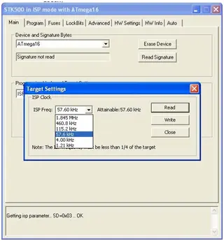
In certain cases, especially when working with a new microcontroller, it may be required to temporarily use a lower programming frequency, such as 57.6 kHz, in order to correctly set the fuses. Once the fuses are programmed, it is essential to revert to the original frequency of 1.845 MHz before proceeding with the microcontroller programming.
Source: Introduction to the Atmel ATmega16 Microcontroller
- How should static charges be dissipated before handling circuit boards?
Use an Electrostatic Discharge wrist strap connected to a grounded earth source or touch a well-grounded metal surface. - What is the recommended ISP frequency relative to the ATmega16 clock speed?
The ISP frequency must be less than one-quarter of the ATmega16's clock speed, such as 1.843 MHz for an 8 MHz clock. - Which headers are connected by the 6-pin ISP ribbon cable?
The cable connects the ISP6PIN header on the STK500 to the SPROG3 header. - What software tools are required for compiling and transferring programs?
WinAVR and AVR Studio are the specified freeware tools for writing, compiling, and managing files. - How do you configure the default jumper settings on the STK500?
Jumpers connect two pins for ON status; for OSCSEL, connect the two right-most pins of the three to select the on-board clock. - What steps resolve an ISP Mode Error when programming a new chip?
Temporarily set the ISP frequency to 57.6 kHz to program fuses, then reset it to 1.845 MHz. - Which connector is used to view output on the PC monitor?
The RS232 SPARE connector is used after disconnecting from the RS232 CTRL connector. - What specific pins link the UART0 port to the RS232 SPARE header?
Pins PD0 and PD1 of PORTD are linked to the RXD and TXD pins on the RS232 SPARE header respectively.