Summary of LCD Interfacing with AVR
This article details interfacing a character LCD with AVR microcontrollers (Atmega8/32) in 8-bit mode. It covers hardware connections using a potentiometer for contrast and resistor for backlight, along with C code for data/command transmission. Two code versions are provided: a basic version sending individual characters and an advanced version with string and integer printing functions. The guide explains necessary delay loops to ensure LCD execution stability and defines hexadecimal commands for initialization.
Parts used in the Interfacing LCD Display in 8bit Mode:
- AVR Microcontroller (Atmega8 or Atmega32)
- LCD Display Module
- Potentiometer (2 to 5 K Ohm)
- Resistor
- Circuit Diagrams
Interfacing LCD Display in 8bit Mode
I’ve already discussed about the LCD display in a note here in this website. You can read the Note on character LCD Display here. Now let us come to the interfacing side of LCD. Let us see the 8bit mode interfacing of the LCD display with an AVR micro controller first. I have added two circuits in this post 1) Interfacing LCD with Avr Atmega8 and 2) Interfacing with Atmega32. Towards the end you can see the real life display as an image where I displayed characters“Circuits Today” ?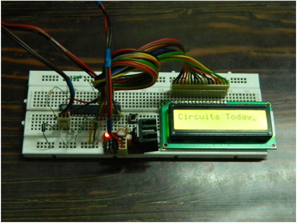
Here to interface LCD with Avr, an 8 bit data bus is required. In addition we need 2 bit control bus for write only mode or 3 bit control bus for Read plus write mode. Connect pin 1 of the LCD module to ground, pin 2 to +ve supply. Connect a Pot (2 to 5 K Ohm) across the supply and ground. Connect the middle pin of the pot to pin3 of LCD module. If you want to light up the back light, connect the –LED pin to ground. Connect the +LED pin of the LCD to the +ve supply using a resistor. Figure below is the two circuit diagrams!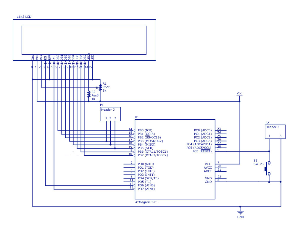
LCD Interfacing-Atmega32
Now, I’ve written up two routines for two separate cycles. One is used to transfer data (or character). Another sends command. In C code, they are listed under the functions ‘LCD()’ and ‘LCDcmd()’ respectively. To prevent crash of data, we must allow the LCD to complete execution of each operation. Here we will be using delay loops available from the AVR studio Library. Each instruction or data takes at least 40uS to get executed. Longest wait loop is of 1.65mS. For further details, read my note upon LCD display (Wait a minute. It shouldn’t be ‘LCD display’, instead ‘LC display’. But ‘LCD display’ is widely used ) & AVR Library overview for beginners. Let’s check the code
One more thing, it is better that to copy and paste this code in notepad (Or word pad or MS word) and check this code.
//-------------------------------------------------------- Start

#include

#include
#define DPORT PORTB //Define Data port
#define DPDDR DDRB
#define CPORT PORTD //Define Signals port
#define CPDDR DDRD
#define RS PD6 //Signal Pins, Reset
#define EN PD7 //Signal Pins, Enable
//Pre-defining Commands
#define LCDClear 0x01 //Clears LCD Display
#define LCD8bit 0x38 //Sets up LCD in 8bit mode
#define LCDCursorOn 0x0f //Enables Cursor
#define LCDSeek00 0x80 //Seeks the pointer to the begeining
void LCD(char ch);
void LCDcmd(void);
void LCDInitialize(void);
int main()
{ DPDDR=0xff;
CPDDR=0xf0;
_delay_ms(2000);
LCDInitialize();
LCD(‘C’);
LCD(‘i’);
LCD(‘r’);
LCD(‘c’);
LCD(‘u’);
LCD(‘i’);
LCD(‘t’);
LCD(‘s’);
LCD(‘ ’);
LCD(‘T’);
LCD(‘o’);
LCD(‘d’);
LCD(‘a’);
LCD(‘y’);
return 0;
}
void LCD(char ch)
{ DPORT=ch; //Put values to ports
CPORT=(1<<RS)|(1<<EN); //Signaling to send data
_delay_us(10);
CPORT=(1<<RS)|(0<<EN);
_delay_us(45);
}
void LCDcmd(char ch)
{ DPORT=ch;
CPORT=(0<<RS)|(1<<EN); //Signaling to send commands
_delay_ms(10);
CPORT=(0<<RS)|(0<<EN);
_delay_ms(45);
if(ch==0x01||ch==0x02) // If commands are LCD Clear or
// LCDSeek00, delay 2mS
_delay_ms(2);
}
void LCDInitialize(void)

{ LCDcmd(LCD8bit);

LCDcmd(LCDCursorOn);

LCDcmd(LCDClear);

LCDcmd(LCDSeek00);

}

//-------------------------------------------------------- End
Now I’ve used Lots of crazy symbols in my program. Here is a summary.
- In C, ‘0x’ prefix represents a hexadecimal number. ‘0b’ represents binary.
- ‘|’ is the bitwise ‘OR’ operation. Here, 0b0010|0b0110=0b0110.
- ‘||’ is the Logical ‘OR’ test. If in statement ‘A||B’, if value of either or both of the operand is NOT Zero (or True), then the statement result is TRUE.
- ‘≪’ stands for Bitwise right shift operation. Here, 0b0001≪2 =0b0100.
- ‘≫’ stands for Bitwise left shift operation. Here, 0b1000≫1 =0b0100. Just for your knowledge, I’ve not used them in this article.
So that was basic version of the code. Let’s see some better functions to be compiled.
//-------------------------------------------------------- Start

#include

#include
#define DPORT PORTB //Define Data port
#define DPDDR DDRB
#define CPORT PORTD //Define Signals port
#define CPDDR DDRD
#define RS PD6 //Signal Pins, Reset
#define EN PD7 //Signal Pins, Enable
#define LCDClear 0x01 //Clears LCD Display
#define LCD8bit 0x38 //Sets up LCD in 8bit mode
#define LCDCursorOn 0x0f //Enables Cursor
#define LCDSeek00 0x80 //Seeks the pointer to the begeining
void LCD(char ch);
void LCDcmd(void);
void LCDInitialize(void);
void printStringLCD(char *str);
int printIntLCD(unsigned int i);
int main()
{ DPDDR=0xff;
CPDDR=0xf0;
_delay_ms(500);
LCDInitialize();
printStringLCD(“Circuits Today”);
_delay_ms(5000);
LCDcmd(LCDClear);
prinStringLCD(“Print an Integer”);
LCDcmd(0xc0);
printIntLCD(990);
return 0;
}
void LCD(char ch)
{ DPORT=ch; //Put values to ports
CPORT=(1<<RS)|(1<<EN); //Signaling to send data
_delay_us(10);
CPORT=(1<<RS)|(0<<EN);
_delay_us(45);
}
void LCDcmd(unsigned char ch)
{ DPORT=ch;
CPORT=(0<<RS)|(1<<EN); //Signaling to send commands
_delay_us(10);
CPORT=(0<<RS)|(0<<EN);
_delay_us(45);
if(ch==0x01||ch==0x02)
_delay_ms(2);
}
void LCDInitialize(void)
{ LCDcmd(LCD8bit);
LCDcmd(LCDCursorOn);
LCDcmd(LCDClear);
LCDcmd(LCDSeek00);
}
void printStringLCD(char *str)

{ int i=0;

while(str[i]!='\0')

{ DPORT=str[i]; //Put values to ports

LCD(ch);

i++;

}

}

int printIntLCD(unsigned int i)

{ static int a;

a=0;

if(i!=0)

{ printIntLCD(i/10);

LCD(‘0’+i%10);

a++;

}

return a;

}

//-------------------------------------------------------- End
For more detail: LCD Interfacing with AVR
- What type of bus is required to interface LCD with AVR?
An 8 bit data bus is required, along with a 2 bit control bus for write only mode or a 3 bit control bus for read plus write mode. - How should pin 1 and pin 2 of the LCD module be connected?
Pin 1 must be connected to ground and pin 2 to the positive supply voltage. - What component connects to pin 3 of the LCD module?
The middle pin of a potentiometer ranging from 2 to 5 K Ohm connects to pin 3. - How do you light up the back light of the LCD?
Connect the negative LED pin to ground and the positive LED pin to the positive supply using a resistor. - What is the minimum time required for each instruction or data to get executed?
Each instruction or data takes at least 40 microseconds to get executed. - Which function is used to transfer data or characters in the C code?
The function named LCD is used to transfer data or characters. - What does the prefix 0x represent in the C program?
In C, the 0x prefix represents a hexadecimal number. - How does the bitwise OR operation work in this context?
The | symbol is the bitwise OR operation where combining binary values like 0b0010 and 0b0110 results in 0b0110. - What command sets up the LCD in 8 bit mode?
The command defined as LCD8bit with value 0x38 sets up the LCD in 8 bit mode. - How can you seek the pointer to the beginning of the display?
You use the command LCDSeek00 with value 0x80 to seek the pointer to the beginning.