Summary of An AVR-Based Microstepping Bipolar Chopper Stepper Motor Driver (STMD)
This article describes an open-source, hobbyist-friendly stepper motor driver (STMD) using DIP switches for selectable microstepping modes. It features optically isolated signals, adjustable current limits, automatic idle current reduction, and motor braking options. The design utilizes an Atmel Mega48 microcontroller and DMOS driver chips, with all parts available at Digikey.
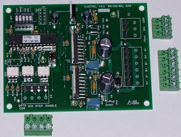
Parts used in the STMD Project:
- Atmel Mega48 microcontroller
- National Semiconductor LMD18245T DMOS Full-Bridge Motor driver chips
- DIP switches (SW1 through SW5)
- Potentiometers (R4 and R5)
- Resistors (R2, R3, R8, R9, R10, R11)
- Jumpers (JP1, JP2)
- Removable screw terminals
- Status LED
- Double-sided printed circuit board
- Heat sink and mounting hardware
Features
- Open Source – The schematic, parts list, and software are all freely downloadable!
- Hobbyist-friendly – No surface mount parts means allows this drive to be easily repaired!
- DMOS driver chips rated at 55V and 3 Amps.
- Easy parts availability – Electronic parts are all available at Digikey. Just add your own heat sink and mounting hardware.
- DIP Switch selectable modes of stepping:
- Full Step, Both Phases On
- Full Step, Wave Drive
- Half Step
- Quarter Step
- Sixth Step
- Eighth Step
- Tenth Step
- Twelfth Step
- Sixteenth Step (available on special request in place of Twelfth Step mode with a special version of firmware)

- Optically isolated step, direction, & enable signals.
These signals are ground referenced so no +5VDC is required – hook directly to your parallel port. - Selectable automatic idle current reduction to reduce motor heating.
Motor current can be reduced if no steps are received for 3 seconds. Oscilloscope Image, 202 kb - DIP switch selectable motor test mode.
Allows for testing of motor/drive/wiring without an externally generated step signal. - Motor braking can be activated when drive is disabled.
Alternatively, motor braking can also be disabled such that the motor will freewheel when drive is disabled. - Motor current is adjustable by two potentiometers. (One for each motor phase)
Fixed resistors may be substituted in place of the potentiometers for cost savings or increased reliability. - Removable screw terminals for all wiring connections.
- Status LED flashes during normal operation to let the user know the microcontroller is running.
Illuminates solid during a fault condition. - Quality double-sided printed circuit board with ground plane and silkscreen legend.
Board size is 3.25″ x 4.30″ with mounting holes for #6 screws in each corner.
Design & Configuration
- An Atmel Mega48 running on its internal 8 MHz oscillator is the brain of the system. A 10 pin ISP connector is provided in the event the user would like to modify the open source firmware. The program memory is only about 40% full so there is plenty of room for an enterprising user to add to the custom features and functions. Normal operation of the microcontroller is indicated by flashing of the ‘alive’ LED once per second. If a fault condition is detected, the LED will be latched on until power is cycled to the board.
- For power switching, National Semiconductor’s LMD18245T 3A, 55V DMOS Full-Bridge Motor driver chips are used. These driver chips are the most expensive part of the STMD as two of them are required per motor. Although these driver chips are rated for +55 VDC, allowance should be made for back emf from the motor. As such, I recommend a maximum of +45 VDC.
- For flexibility, DIP switches are used to select the mode of stepping. As described below, eight modes of stepping are available.
SW3 SW2 SW1 Stepping Mode Steps/Revolution Off Off Off Full, Both Phases On 200 Off Off On Full, One Phase On 200 Off On Off Half 400 Off On On Quarter 800 On Off Off Sixth 1200 On Off On Eighth 1600 On On Off Tenth 2000 On On On Twelfth/Sixteenth* 2400/3200 *Sixteenth step mode requires a special firmware version which is available upon special request and also in the open source firmware.
- SW4 in conjunction with JP1 and two pull-up/down resistors selects the method of motor braking.
- SW4 off, JP1 on, pull-up resistor R10 populated – Motor braking active when drive is disabled.
- SW4 on, JP1 on, pull-up resistor R10 populated – Motor is allowed to freewheel when drive is disabled.
- JP1 off and pull-down resistor R11 populated – Motor braking always disabled.
- All other combinations of SW4, JP1 and pull-up/down resistors are invalid and drive operation is undefined. DO NOT populate both R10 and R11!
- SW5 is used to enable test mode. This allows the user to test their wiring and drive/motor operation with no external step signal. During test mode, the drive will internally generate a step signal to rotate the motor at approximately 1 revolution per second. The drive must be enabled and will respond to the direction pin. To enable the drive with no external enable signal, you can temporarily connect J1-3 (Com) to J3-1 (Opto Com) and J1-1 (+5Vout) to J3-4 (Enable). The motor will change directions if J1-1 (+5Vout) is connected to J3-2 (Direction).
- JP2 is used to enable/disable automatic idle current reduction. When JP2 is on, idle current is reduced when no step signal has been received for 3 seconds. Full motor current is restored upon the next step signal. The amount of idle current reduction can be manipulated by changing R9 in the R8/R9 voltage divider. The default value of 1k allows for a 50% reduction. Using a 2k in place of R9 will allow for a 33% reduction.
- Current Limiting is set by adjusting potentiometers R4 and R5. The resistance as seen from pin 13 to ground on each of the LMD18245T driver chips (test points 6 & 7) should be set to 18750/I where I is the maximum desired winding current. (Where this comes from?) R2 and R3 (6.2 kohm resistors) are in series with the potentiometer to prevent the motor current from being set higher the driver chip’s maximum rated load current. Potentiometers R4 and R5 should be set to identical values. Here is a picture (246 kb) showing how to adjust R4 when measuring from TP6.
For more detail: An AVR-Based Microstepping Bipolar Chopper Stepper Motor Driver (STMD)
- Optically isolated step, direction, & enable signals.
- What is the maximum recommended voltage for the drive?
The author recommends a maximum of +45 VDC to allow for back EMF from the motor, even though the driver chips are rated for +55 VDC. - Can I modify the firmware on this project?
Yes, a 10 pin ISP connector is provided for users who wish to modify the open source firmware. - How do I enable test mode without an external step signal?
Set SW5 to enable test mode, which internally generates a step signal to rotate the motor at approximately 1 revolution per second. - Does the system support automatic idle current reduction?
Yes, when JP2 is enabled, idle current is reduced if no step signal has been received for 3 seconds. - How is the motor current adjusted?
Motor current is adjustable by two potentiometers, one for each motor phase, or fixed resistors can be substituted. - What stepping modes are available via DIP switches?
Eight modes are available including Full Step, Half Step, Quarter Step, Sixth Step, Eighth Step, Tenth Step, Twelfth Step, and Sixteenth Step. - Can the motor freewheel when the drive is disabled?
Yes, by configuring SW4, JP1, and specific pull-up/down resistors, the motor can be set to freewheel instead of braking. - Are surface mount parts required for this project?
No, the design is hobbyist-friendly and does not use surface mount parts, making it easy to repair.