Summary of Lighting Up Your World: The Atmel AVR Microcontroller LED Chasing Project
This article details an LED chasing effect project using the AVR ATMega168 microcontroller. It compares three programming approaches: standard Arduino IDE code, optimized Arduino-style bit manipulation, and a full C implementation in Atmel AVR Studio to minimize code size. The project demonstrates how to control eight LEDs with variable speed via a trimpot while familiarizing users with different Integrated Development Environments (IDEs) like Arduino and AVR Studio.
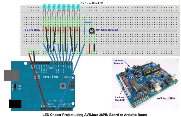
Parts used in the LED Chasing Project:
- AVRJazz 28PIN board or Arduino board
- Eight 470 Ohm resistors
- Eight 3 mm LEDs
- 10K Ohm trimmer potentiometer
- Breadboard
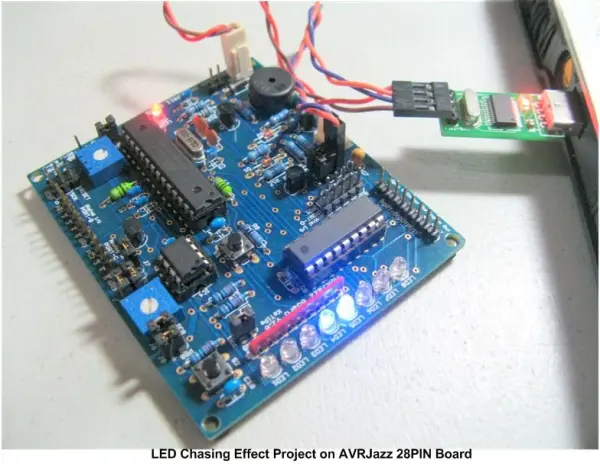
Building the LED chasing effect stands out as an engaging project for many beginners and enthusiasts in the embedded systems domain or hobbyist circles. This project entails leveraging both the Arduino IDE and Atmel AVR Studio to program the AVR ATMega168 microcontroller, thereby offering an opportunity to familiarize oneself with these widely recognized Integrated Development Environments (IDEs) for project programming.
The LED Chasing Project
To undertake this project, you will require either the AVRJazz 28PIN board available from the ermicro store or an Arduino board along with eight 470 Ohm resistors, eight 3 mm LEDs, a 10K Ohm trimmer potentiometer (trimpot), and a breadboard, as depicted in the image below:
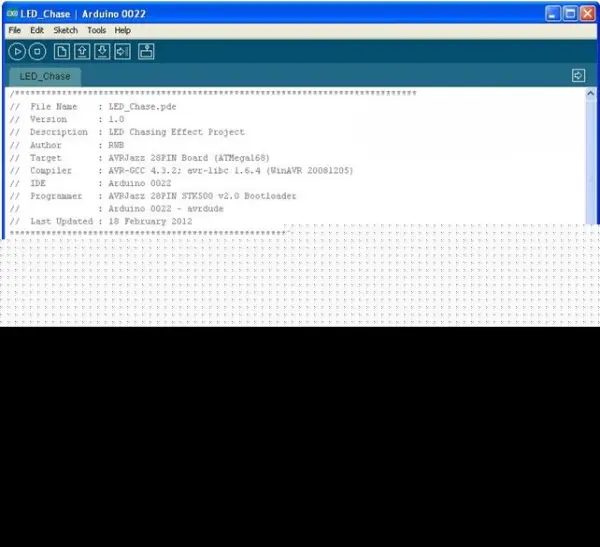
Now let’s start with the Arduino sketch first version of the LED Chasing Effect:
/*****************************************************************************
// File Name : LED_Chase.pde
// Version : 1.0
// Description : LED Chasing Effect Project
// Author : RWB
// Target : AVRJazz 28PIN Board (ATMega168)
// Compiler : AVR-GCC 4.3.2; avr-libc 1.6.4 (WinAVR 20081205)
// IDE : Arduino 0022
// Programmer : AVRJazz 28PIN STK500 v2.0 Bootloader
// : Arduino 0022 - avrdude
// Last Updated : 18 February 2012
*****************************************************************************/
byte LEDPin[]={0,1,2,3,4,5,6,7};
char LEDDirection=1;
char LEDOn=0;
unsigned int LEDDelay;
void setup() {
// Set the digital PIN (0-7) to the Output Mode
for (byte count=0; count <= 7; count++) {
pinMode(LEDPin[count],OUTPUT);
}
}
void loop() {
// Turn off all the digital Output (0 - 7)
for (byte count=0; count <= 7; count++) {
digitalWrite(LEDPin[count],LOW);
}
// Turn ON one LED
digitalWrite(LEDPin[LEDOn],HIGH);
// Changed to the next LED
LEDOn += LEDDirection;
// Change the direction when reach 0 or 7
if (LEDOn >= 7)
LEDDirection=-1;
if (LEDOn <= 0)
LEDDirection=1;
// LED Chasing Delay
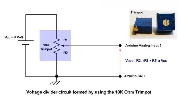
LEDDelay=analogRead(0); // Select Analog PIN 0 for the Trimpot Input
delay(LEDDelay);
}
/* EOF: LED_Chase.pde */

Once the setup() function is invoked during program execution, the Arduino library proceeds to continuously call the loop() function. Consequently, we integrate the LED chasing effect algorithm along with analog input reading within this function.
// LED Chasing Delay
LEDDelay=analogRead(0); // Select Analog PIN 0 for the Trimpot Input
delay(LEDDelay);
The trimpot will function as the voltage divider circuit and supply the varying voltage input (0 to 5 volt) to the Arduino board analog input 0.
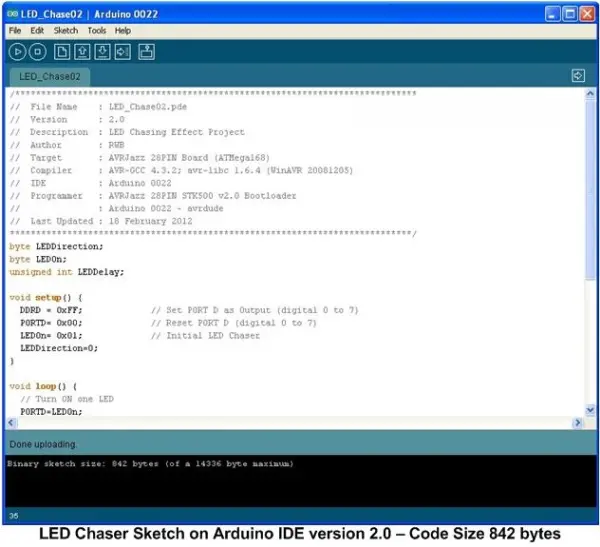
Upon compiling the LED chasing program, the resulting Intel HEX code size is approximately 1236 bytes. Here, we present a more concise version of the code in Intel HEX format, totaling 842 bytes. This version utilizes a “Non Arduino” methodology for manipulating the digital output port to achieve the LED chasing effect.
/*****************************************************************************
//  File Name    : LED_Chase02.pde
//  Version      : 2.0
//  Description  : LED Chasing Effect Project
//  Author       : RWB
//  Target       : AVRJazz 28PIN Board (ATMega168)
//  Compiler     : AVR-GCC 4.3.2; avr-libc 1.6.4 (WinAVR 20081205)
//  IDE          : Arduino 0022
//  Programmer   : AVRJazz 28PIN STK500 v2.0 Bootloader
//               : Arduino 0022 - avrdude
//  Last Updated : 18 February 2012
*****************************************************************************/
byte LEDDirection;
byte LEDOn;
unsigned int LEDDelay;
void setup() {
DDRD = 0xFF; // Set PORT D as Output (digital 0 to 7)
PORTD= 0x00; // Reset PORT D (digital 0 to 7)
LEDOn= 0x01; // Initial LED Chaser
LEDDirection=0;
}
void loop() {
// Turn ON one LED
PORTD=LEDOn;
// Change the direction when reach 0 or 7
if (LEDDirection == 0) {
LEDOn=LEDOn << 1; // Shift Left 1 Bit
if (LEDOn >= 0x80) LEDDirection=1;
} else {
LEDOn=LEDOn >> 1; // Shift Right 1 Bit
if (LEDOn <= 0x01) LEDDirection=0;
}
// LED Chasing Delay
LEDDelay=analogRead(0); // Select Analog PIN 0 for the Trimpot Input
delay(LEDDelay);
}
/* EOF: LED_Chase02.pde */
Utilizing direct port manipulation offers the advantage of achieving a more compact code compared to the initial version. Within the setup() function, the DDRD register of the AVR ATMega168/328 microcontroller is employed to configure the I/O mode (digital pins 0 to 7) of the PORTD.
DDRD = 0xFF; // Set PORT D as Output (digital 0 to 7) PORTD= 0x00; // Reset PORT D (digital 0 to 7)
The hexadecimal notation 0xFF corresponds to the decimal value of 255, or “1111 1111” in binary format. When we assign the binary value “1111 1111” to the DDRD register, we are directing the AVR ATMega168/328 microcontroller to set the PORTD mode to output mode.
In this iteration, we employ the algorithm utilizing the “shift left” and “shift right” bit manipulation operators to replicate the LED chasing effect demonstrated in the initial version. The functionality of the bit manipulation shift operator involves shifting one bit left or right sequentially, as illustrated in the accompanying image below:
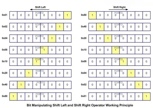
By incrementing or decrementing one bit at a time (either left or right), we can achieve the desired LED chasing effect instead of simply turning off all LEDs and turning on a single LED as demonstrated in the initial code. The subsequent C code illustrates the variances between these two algorithms:
The first version:
// Turn off all the digital Output (0 - 7)
for (byte count=0; count <= 7; count++) {
  digitalWrite(LEDPin[count],LOW);
}

// Turn ON one LED
digitalWrite(LEDPin[LEDOn],HIGH);

// Changed to the next LED
LEDOn += LEDDirection;
The second version:
 // Turn ON one LED
 PORTD=LEDOn;
// Change the direction when reach 0 or 7
if (LEDDirection == 0) {
LEDOn=LEDOn << 1; // Shift Left 1 Bit
if (LEDOn >= 0x80) LEDDirection=1;
} else {
LEDOn=LEDOn >> 1; // Shift Right 1 Bit
if (LEDOn <= 0x01) LEDDirection=0;
}
Consequently, employing the second algorithm yields streamlined code and significantly reduces the size of the Intel HEX file, making it easier to load into the AVR microcontroller’s flash RAM.
The AVR Studio IDE
In the final example, we will employ a comprehensive C code within Atmel AVR Studio to execute this LED chasing project. I have adopted the “arduino style” approach, utilizing functions such as setup(), loop(), and analogRead() to enhance comprehension. The entire program for the LED chasing project is depicted in the following C code snippet:
//***************************************************************************
//  File Name    : LED_Chase03.c
//  Version      : 3.0
//  Description  : ACRJazz 28PIN AVR ATMega168 Demo Program
//  Author       : RWB
//  Target       : AVRJazz 28PIN Board (ATMega168)
//  Compiler     : AVR-GCC 4.5.1; avr-libc 1.7.1 (AVR Studio 5 ToolChain)
//  IDE          : Atmel AVR Studio 5.0.1223
//  Programmer   : AVRJazz Mega168 STK500 v2.0 Bootloader
//               : AVR Visual Studio 5.0.1223, STK500 programmer
//  Last Updated : 18 February 2012
//***************************************************************************
#define F_CPU 16000000UL      // AVRJazz 28PIN Used 16MHz
#include <avr/io.h>
#include <util/delay.h>

// Define byte to unsigned char
typedef unsigned char byte;

// Delay Function Implementation for avr-libc 1.7.1
void delay(unsigned int __ms)
{
  while(__ms--) {
    _delay_us(450);           // 2 x 450us for emulating 1 ms delay
    _delay_us(450);
  }
}

// Analog Read Function Implementation
unsigned int analogRead(unsigned char __anPort) {
  // Disable digital input on __anPort
  DIDR0 |= (1 << __anPort);

  // Select ADC Channel using ADMUX Register on ATMega168
  // Use internal Voltage Reference (REFS1=0 and REFS0=0)
  // ALAR bit is 0 for Right Justified Result
  ADMUX=__anPort;

  // Start conversion by setting the ADSC bit on ADCSRA Register
  ADCSRA |= (1 << ADSC);

  // Wait until convention complete ADSC=0 -> Complete
  while (ADCSRA & (1 << ADSC));

  return ADCW;             // Return the ADC Value
}

// Start the C Main Function
void main(){
  setup();                 // Call the setup() function

  // Enable the ADC Peripheral using ADCSRA Register on AVR ATMega168
  // ADC Prescaler: 128 (ADPS2=1, ADPS1=1, and ADPS0=1)
  ADCSRA = (1<<ADEN) | (1<<ADPS2) | (1<<ADPS1) | (1<<ADPS0);
  ADCSRB = 0x00;           // Free Running Mode ADC

  for(;;) {
    loop();                // Call the loop() function
  }
  return 0;
}

// Start the LED_Chase02.pde program on Arduino IDE
byte char LEDDirection;
byte char LEDOn;
unsigned int LEDDelay;

void setup() {
  DDRD = 0xFF;             // Set PORT D as Output (digital 0 to 7)
  PORTD= 0x00;             // Reset PORT D (digital 0 to 7)

  LEDOn= 0x01;             // Initial LED Chaser
  LEDDirection=0;
}

void loop(){
  // Turn ON one LED
  PORTD=LEDOn;

  // Change the direction when reach 0 or 7
  if (LEDDirection == 0) {
    LEDOn=LEDOn << 1;      // Shift Left 1 Bit
    if (LEDOn >= 0x80) LEDDirection=1;
  } else {
    LEDOn=LEDOn >> 1;      // Shift Right 1 Bit
    if (LEDOn <= 0x01) LEDDirection=0;
  }

  // LED Chasing Delay
  LEDDelay=analogRead(0);  // Select Analog PIN 0 for the Trimpot Input
  delay(LEDDelay);
}

/* EOF: LED_Chase03.c */
In the provided LED_Chase03.c program listing, it’s evident that the C code within the setup() and loop() functions bears resemblance to the LED_Chase02.pde in the Arduino IDE. In the AVR Studio’s C code version (utilizing version 5), we include essential elements such as headers, definitions, typedefs, and functions to ensure the proper functionality of the setup() and loop() functions.
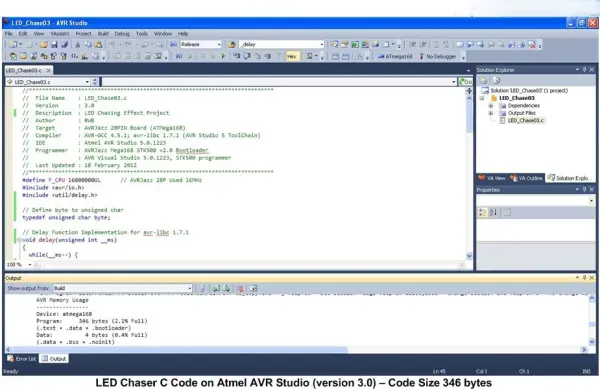
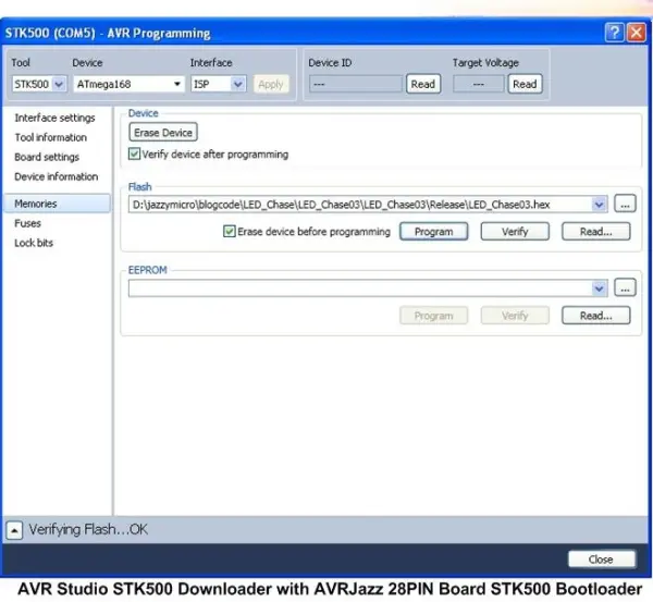
Utilizing a complete C code within Atmel AVR Studio allowed us to notably diminish the HEX size to 346 bytes in contrast to the HEX code generated by the Arduino library in our subsequent iteration of the LED chasing program. For comprehensive insights into utilizing the analog peripheral on the Atmel AVR microcontroller, I recommend referring to the article titled “Analog to Digital Converter AVR C Programming.”
I trust this modest project will illuminate your understanding of embedded systems and inspire further exploration into the realm of embedded systems.
- What hardware is required to build this project?
You need an AVRJazz 28PIN board or an Arduino board, eight 470 Ohm resistors, eight 3 mm LEDs, a 10K Ohm trimmer potentiometer, and a breadboard. - How does the trimpot affect the LED chasing effect?
The trimpot acts as a voltage divider supplying varying voltage from 0 to 5 volts to analog input 0, which controls the delay speed of the LEDs. - Can I use Atmel AVR Studio for this project?
Yes, you can use a complete C code within Atmel AVR Studio to execute the project, utilizing functions similar to the Arduino style. - Which method produces the smallest Intel HEX file size?
Using a complete C code within Atmel AVR Studio yields the smallest size at 346 bytes compared to the other versions. - How does the second version of the code differ from the first?
The second version uses direct port manipulation and bit shift operators instead of turning off all LEDs before turning on one. - What is the purpose of the DDRD register in the setup function?
The DDRD register is used to configure the I/O mode of digital pins 0 to 7 as output mode by assigning the binary value 1111 1111. - Does the project support changing the direction of the chase?
Yes, the algorithm changes direction when the LED index reaches 0 or 7 to create a back-and-forth chasing effect. - Which IDEs are mentioned for programming the microcontroller?
The article mentions the Arduino IDE and Atmel AVR Studio as the two widely recognized Integrated Development Environments used.