Summary of Line Follower Robot using AVR Microcontroller ATmega16
This article details the construction of a Line Follower Robot using an AVR Atmega16 microcontroller. The robot utilizes two IR sensors to detect a black line on a surface and controls two DC motors via an L293D driver to follow the path, stop at intersections, and correct its trajectory. The system relies on logic where sensor readings determine motor direction: forward if no line is detected, turning left or right if one side detects the line, and stopping if both sensors detect the line simultaneously.
Parts used in the Line Follower Robot:
- DC Gear Motors (2 units)
- IR sensor module (2 units)
- L293D Module
- Wireless Power Source (e.g., Battery, Power bank)
- Robot Chassis
- Atmega16 Microcontroller IC
- 16Mhz Crystal Oscillator
- Two 100nF Capacitors
- Two 22pF Capacitors
- Push Button
- Jumper Wires
- Breadboard
- USBASP v2.0
Here we will be building yet another project with AVR Atmega16 Microcontroller. If you are new to AVR microcontrollers then you can refer to previous AVR projects and tutorials.
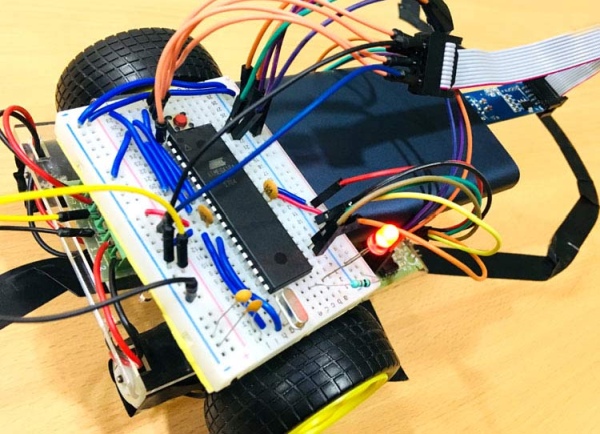
Building a robot is always a thrill for all electronics hobbyists. And this thrill can be maximized if the robot can automatically do some things without any external instructions. One of the most commonly built robot by electronics beginners is Line Follower Robot. As the name suggests robot will follow line drawn on the surface. The line need not be a straight line. Also, lines can be of any colours.
We previously built Line Follower Robot projects using different Controllers:
- Line Follower Robot using 8051 Microcontroller
- Line Follower Robot using PIC Microcontroller
- Line Follower Robot using Arduino
- Line Follower Robot using Raspberry Pi
- Line Follower Robot Using MSP430 Launchpad
Today we will use AVR microcontroller to build a Line follower Robot.
Mostly IR sensors are used to detect lines. The IR sensors are good in detecting white or black surfaces. Although you can use other sophisticated sensors which will be able to detect all colours and can make a robot which can follow all colour lines. The robot should be able to detect line even if the path is altered by changing the angle and keep following the line. Also, it should stop wherever the stop zone comes in the line.
Line follower robots are used extensively now a days in manufacturing industries, medical, domestic applications and goods warehouse. The robots are not limited to only these applications and can extend its applications in many future applications.
Concept of Line Follower Robot
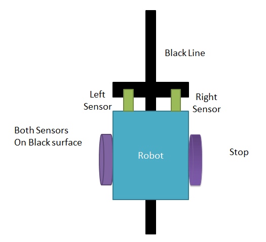
The IR sensors are key player in this project. IR sensors are placed in front side of the robot to track the drawn black line and the surface. The robot is placed in between the line and with the help of IR sensors the robot keeps track of the line. IR sensors feedback the reading to microcontroller and with the help of IR reading, the microcontroller move motors left side or right side and again brings the robot to the path.
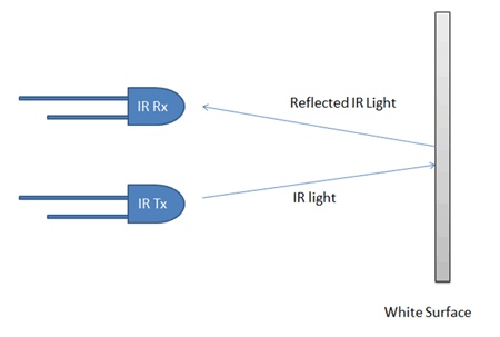
Line Follower Robot is able to track a line with the help of an IR sensor. This sensor has a IR Transmitter and IR receiver. The IR transmitter (IR LED) transmits the light and the Receiver (Photodiode) waits for the transmitted light to return back. An IR light will return back only if it is reflect by a surface. Whereas, all surfaces do not reflect an IR light, only white the colour surface can completely reflect them and black colour surface will completely observe them as shown in the figure below. Learn more about IR sensor module here.
Now we will use two IR sensors to check if the robot is in track with the line and two motors to correct the robot if its moves out of the track. These motors require high current and should be bi-directional; hence we use a motor driver module like L293D. We will also need a Microcontroller like ATmega16 to instruct the motors based on the values from the IR sensor. A simplified block diagram of the same is shown below.
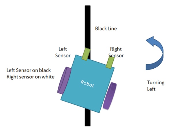
These two IR sensors will be placed one on either side of the line. If none of the sensors are detecting a black line then AVR microcontroller instructs the motors to move forward as shown below
If left sensor comes on black line then the microcontroller instructs the robot to turn left by rotating the right wheel alone.
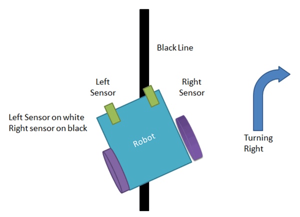
If right sensor comes on black line then the microcontroller instructs the robot to turn right by rotating the left wheel alone.
If both sensors comes on black line, robot stops.
This way the Robot will be able to follow the line without getting outside the track. Now let us see how the circuit and Code looks like.
Components Required
- DC Gear Motors(2 units)
- IR sensor module(2 units)
- L293D Module
- Wireless Power Source(e.g. Battery, Power bank)
- Robot Chaises
- Atmega16 Microcontroller IC
- 16Mhz Crystal Oscillator
- Two 100nF Capacitors
- Two 22pF Capacitors
- Push Button
- Jumper Wires
- Breadboard
- USBASP v2.0(To program Atmega16)
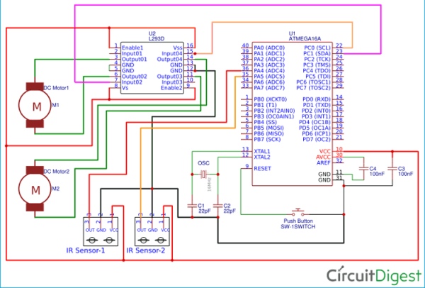
Circuit Diagram
Connect all the components as shown below in the Circuit Diagram
Programming Atmega16 for Line Follower Robot
Here the Atmega16 is programmed using USBASP and Atmel Studio7.0. If you don’t know that how Atmega16 can be programmed using USBASP then visit the link. Complete Program is given at the end of the project, just upload the program in Atmega16 using JTAG programmer and Atmel Studio 7.0 as explained in previous tutorial.
We have tried to keep the code as short and simple as we can. So we are using Macros and Special function registers in this code.
if(bit_is_clear(PINA,leftSen)){ // check if left sensor is OFF
This statement checks if the PA0 where left sensor is connected is LOW or HIGH.
If you want to learn more about this statement and other macros then go to this link
There are four conditions that we are following to read trough IR sensors. IR sensors are named according to their placement in frontside of the Robot. The left IR is Left sensor and right IR is right sensor. The following conditions will decide the movement of robot.
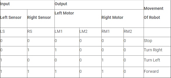
We have written the code according to above conditions. Only change is that we are using only two input pins of the L293D to drive both motors.
Complete code with a demonstration Video is given below.
Code
/* Line Follower Robot Using Atmega16
Circuit Digest(www.circuitdigest.com) */
include
define leftSen PA0 //Connect Left Sensor At PA0
define rightSen PA1 //Connect Right Sensor At PA1
int main(void)
{
DDRA=0xFC; // make PA0,PA1 as input for both sensors 0x0b11111100
DDRC=0xFF; // make Port as output to connect motor pins
while(1)
{
PINA=0x03; //initialize PA0 and PA1
if(bit_is_clear(PINA,leftSen)){ // check if left sensor is OFF
if(bit_is_clear(PINA,rightSen)) { // check if right sensor is OFF
PORTC=0b00000000; // if both sensor zero
} // then stop the robot
else{
PORTC=0b00000001; // if right is ON then take left
}
}
else // check if left sensor in ON
{
if(bit_is_clear(PINA,rightSen)) { // check if right sensor is OFF
PORTC=0b00000010; // it means left sensor is ON
} // so take right
else{
PORTC=0b00000011; // if both sensor is ON
} // then keep moving the robot
}
}
}lse if(blinkFlag == minute)
{
if(count>59)
count=0;
min=count;
}
else if(blinkFlag == month)
{
if(count > 12)
count=1;
mm=count;
}
else if(blinkFlag == date)
{
if(mm == 4 || mm == 6 || mm == 9 || mm == 11)
{
if(count > 30)
count=1;
}
else if(mm == 1 || mm == 3 || mm == 5 || mm == 7 || mm == 8 || mm == 10 || mm == 12)
{
if(count >31)
count=1;
}
else
{
int y=2000+yy;
if(y/4 == 0 && y/400 == 0)
{
if(count > 29)
count=1;
}
else
{
if(count > 28)
count=1;
}
}
dd=count;
}
else if(blinkFlag == year)
{
if(count >99)
count=0;
yy=count;
}
_delay_ms(200);
}
else if(!(downEvent))
{
count–;
if(blinkFlag == year)
{
if(count<0)
count=99;
}
_delay_ms(100);
}
else if(!okEvent)
{
_delay_ms(1000);
return count;
}
}
}
void settingTime()
{
blinkFlag=1;
hr=getPara(hr);
blinkFlag++;
min=getPara(min);
blinkFlag++;
dd=getPara(dd);
blinkFlag++;
mm=getPara(mm);
blinkFlag++;
yy=getPara(yy);
blinkFlag=0;
}
void updateTime()
{
d0=min%10;
d1=min/10;
d2=hr%10;
d3=hr/10;
d4=dd%10;
d5=dd/10;
d6=mm%10;
d7=mm/10;
d8=yy%10;
d9=yy/10;
}
int main(void)
{
unsigned long int Time;
DDRB=0xff;
DDRA=0xE0;
PORTA=0x1E;
DDRD=0xff;
DDRC=0xff;
timer1_init();
while(1)
{
RTC();
updateTime();
_delay_ms(500);
LEDPORT|=1<<secLed;
_delay_ms(500);
LEDPORT&=~(1<<secLed);
if (!setEvent)
{
settingTime();
setTime();
}
}
}
Video
Source: Line Follower Robot using AVR Microcontroller ATmega16
- What components are required to build this project?
The project requires DC gear motors, IR sensor modules, an L293D module, a wireless power source, a robot chassis, an Atmega16 microcontroller, a 16Mhz crystal oscillator, capacitors, a push button, jumper wires, a breadboard, and a USBASP v2.0. - How does the robot detect the line?
The robot uses two IR sensors placed on the front side; the transmitter sends light and the receiver detects reflection, which differs between white and black surfaces. - Which microcontroller is used for this project?
An AVR Atmega16 microcontroller is used to instruct the motors based on values from the IR sensors. - Why is the L293D module used?
The L293D module is used because the motors require high current and must be bi-directional. - What happens when neither sensor detects the black line?
If none of the sensors detect a black line, the AVR microcontroller instructs the motors to move forward. - How does the robot turn when it goes off track?
If the left sensor detects the line, the robot turns left by rotating only the right wheel, and vice versa for the right sensor. - When does the robot stop moving?
The robot stops whenever both sensors come onto the black line simultaneously. - Can this robot follow lines of any color?
While mostly IR sensors detect white or black surfaces, sophisticated sensors can detect all colors, though standard IR sensors work best with black lines on white surfaces.