Hello Builders! The title of this ‘ible is quite simple and so is this project made with the LinkIt One Board. It will detect the amount of light in your surrounding and if its low and motion is detected then turn on the led. This nightlight plugs directly into the wall with the help of a built in 5v power adapter. Its bright enough so that you can go about walking in the dark rather than the low powered night lights.
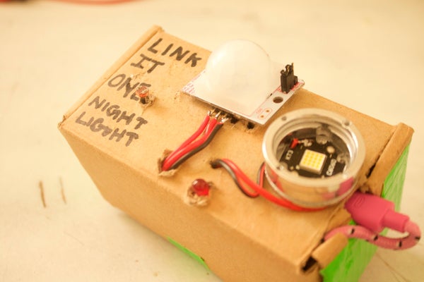
So lets get started with the parts.
Step 1: Parts
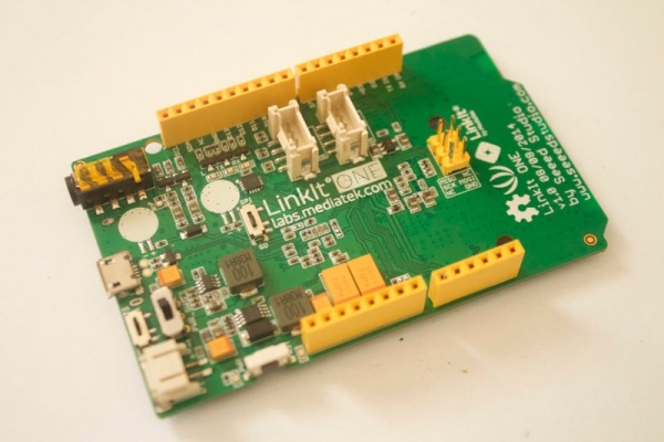
1. LinkIt One Board
2. USB cable
3. 5v Usb Power Brick
4. Small Box
5. PIR motion sensor
6. White LED (Main Light)
7. Red LED ( Indicator )
8. Photoresistor
9. 10k Resistor
10. Perf board(small)
Step 2: Code
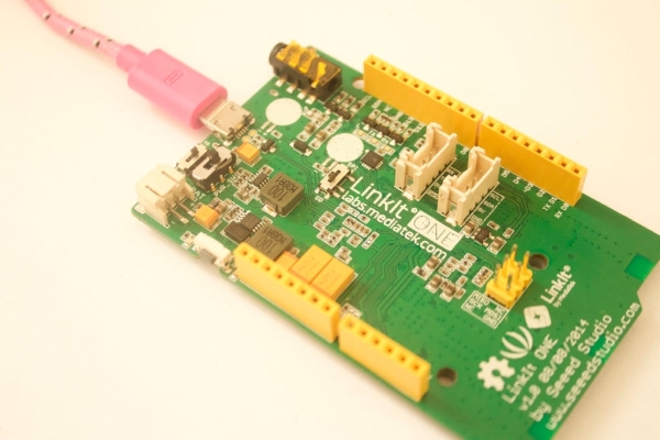
Lets start by coding the Board before building as we are going to build around the board.
This code will turn the LED on based on the amount of light and the motion detected.
Make sure to change the values of the photoresistor based on your room lighting. Here is the code:
int light = 13; // initialize the pins
int motionsensor = 2;
int photoresistor = A1;
int motionval = LOW;
int mval = 0;
int lval;
void setup()
{
Serial.begin(9600); // start communication with the computer
pinMode(photoresistor, INPUT);
pinMode(light, OUTPUT); // declare the pins as outputs or inputs
pinMode(motionsensor, INPUT);
}
void loop()
{
mval = digitalRead(motionsensor);
lval = analogRead(photoresistor);
if(lval < 500) // change this number according to your light val
{
if (mval == HIGH)
{
// if motion is detected then turn the light on
digitalWrite(light, HIGH);
Serial.println(“movement detected”);
}
delay(10);
}
if (motionval == LOW)
{ motionval = HIGH;
}
else
{
digitalWrite(light, LOW);
if (motionval == HIGH)
{
motionval = LOW;
}
}
}
Step 3: Power Brick
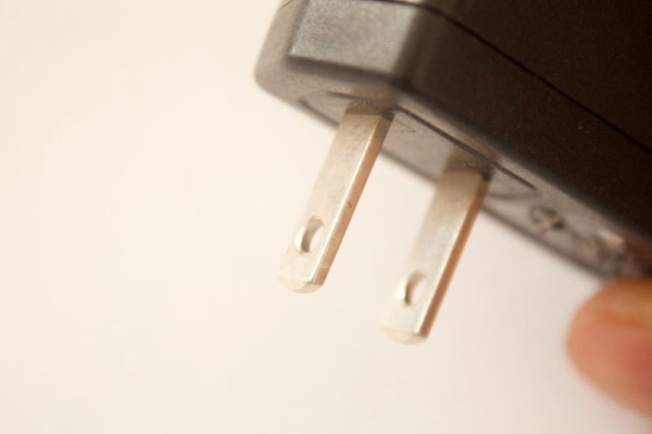
1. Lets start out by make a hole in the box for the points of the power adapter.
2. After making the holes, hot glue the power brick in its place.
3. Insert the USB cable into the power brick.
4. Place the LinkIt One on top of it such that everything sits flush, use very little glue to hold it down as its not going to move much.
Step 4: Photo Resistor
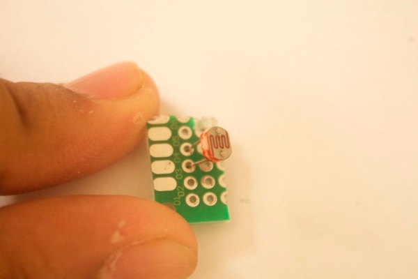
1. Solder the Photoresistor into the perf board.
2. Solder in the resistor to one of the pins of the photoresistor and the second pin of the resistor to GND.
3. Solder a VCC wire to the pin thats not soldered to on the photoresistor.
4. Solder a GND wire to the other end of the resistor.
5. Solder a signal wire to the signal pin( where photoresistor and resistor meet)
Step 5: Solder Wires
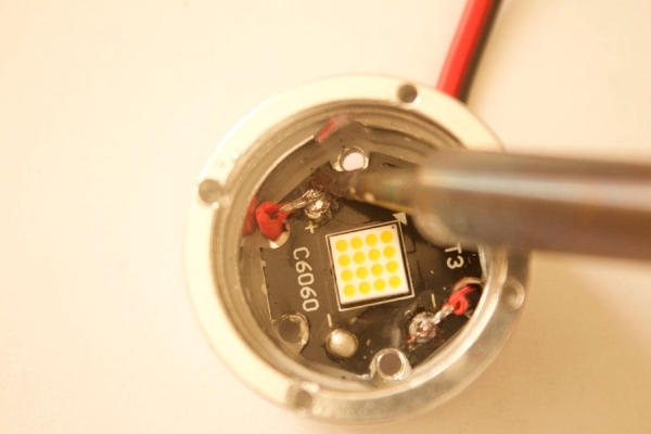
1. Solder wires to the LED. ( VCC and GND)
2. Solder wires to VCC and GND of the motion sensor.
3. Solder the signal wire to the motion sensor.
Step 6: Glue It
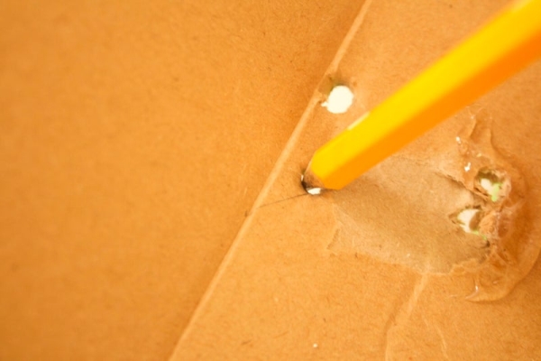
1. Poke holes in the box for the wires to pass through.
2. Glue the Photoresistor on to the base of the top lid of the box. ( Any place where light from your room sufficiently hits the box.
3. Hot Glue the Motion Sensor to the top of the box and put the wires through.
Step 7: Wiring
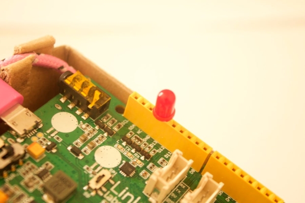
1. Connect the LED to pin 13 and GND.
2. Connect all the GNDs together.
3. Connect the VCC of the photoresistor to 5v.
4. Connect the Red LED to pin 13.
5. Connect the Main LED to pin 2.
6. Connect the signal wire to A1.
And you are done:) Lets test it out now.
Step 8: Test and Conclusion
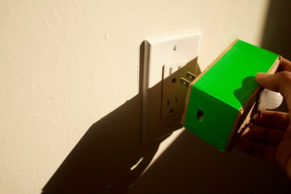
Plug the night light into the wall outlet. Now turn of the light or cover the photoresistor and the LED should light up. If so then you have successfully made the LinkIt One Motion Night Light.
In conclusion this night light could be built upon by adding a relay circuit and attaching a real light bulb instead of an LED. Also the light could be controlled with wifi.
If you have any questions feel free to ask them in the comments.
Source: LinkIt One Motion NightLight
